Radiolocator Kits Available!
Finally a cave radiolocation and thru-the-Earth magnetic communication device that can be assembled by anyone with basic shop and soldering skills, with no test equipment required.
Because of their limited vertical and horizontal range, these radios are intended mainly for use in smaller/shallower caves, locating new entrances, and for demonstrations, practice, etc.
The performance is modest, but a pair can be
constructed in a weekend, and with the two-way
capability they are great fun.
This radio, named the Basic-1, uses a
single dual op-amp IC to perform both receive and transmit
(beacon) functions in one unit. The operating
frequency is 1750 Hz. Transmit can be either CW (Morse
Code) or a beacon pulsing 5 times/second. The loop
antennas are 19 inches (48cm) diameter. A single 9V radio
battery will power a radio for days, even in transmit
mode. A pair of Basic-1
radios can communicate straight down through 200 feet (60
meters) of rock in ideal conditions. Accurate
Radiolocation (which requires a strong signal for sharp
signal nulls) is limited to about 67 feet (20 meters)
depth. Another version of this radio, the Basic-2, uses a second dual op-amp and a heavier loop to improve receiver performance and greatly increase the transmitted signal. The Basic-2 costs significantly more to build because of the high cost of copper wire, and has half the battery life, but increases range to 300 feet (90 meters) for communicating and 100 feet (30 meters) depth for radiolocating. The signal drops off as the cube of range (doubling distance drops the signal to 1/8), which makes long ranges difficult with simple equipment.
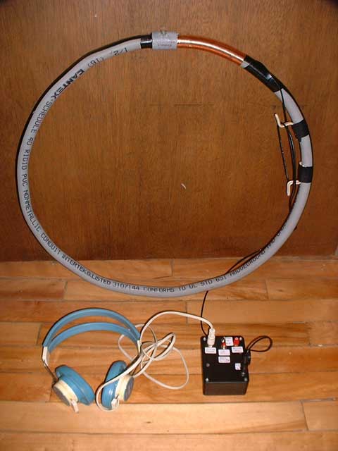
Basic-2 Radiolocator with loop formed from PVC electrical conduit
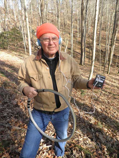
I have
assembled several radios and loop antennas that have
been range-tested on the surface. During testing
in an open field I detected noise from power line
harmonics that I eventually traced to a buried wire
that I was able to radiolocate and follow for hundreds
of feet. The abandoned wire was not connected to
AC power at either end. Apparently, magnetic
fields and/or earth currents from distant power lines
induced current in the wire. Later, I found a
second abandoned wire in an adjacent field! This
is another good use for a sensitive broadband audio
frequency receiver. One successful cave
radiolocation test was done with a Basic-1 in less
than ideal conditions.
I have put together a few kits with most of the required parts including PC board, case, Telex 610 mono 600 Ohm headphones, wire, controls, connectors, knob, and electronic parts, which are 100% thru-hole. Not included is the battery, the bubble levels needed for accurate locating, the loop form, the loop wire, and the optional piezo sounder (a Radio Shack item). Links to documentation for assembly and use are found below. I am looking for feedback to make improvements in the kits and documentation. It would not be difficult for an experienced person to assemble a radio from junk box parts even without the PC board, but some test equipment might be necessary for frequency alignment. I am selling at my cost as a service to the small Cave Radio Community. If there is enough interest, quantity purchases should bring the prices down.
The following costs exclude postage. Contact me for a quote at the email address on the bottom of this page. I will take a personal or bank check, or PayPal. PayPal will be 5% extra if you are paying by credit card rather than withdrawing from a PayPal account. Note that you do not need to have a PayPal account to send money. I will send you the name of my PayPal account.
A single Basic-2 radio kit is $35.00. You must purchase your own loop wire(~$35.00-$45.00) plus 2 bubble levels (~$4.00) bringing the total cost to ~$74.00 not counting the loop frame, optional piezo sounder, or battery.
I have put together a few kits with most of the required parts including PC board, case, Telex 610 mono 600 Ohm headphones, wire, controls, connectors, knob, and electronic parts, which are 100% thru-hole. Not included is the battery, the bubble levels needed for accurate locating, the loop form, the loop wire, and the optional piezo sounder (a Radio Shack item). Links to documentation for assembly and use are found below. I am looking for feedback to make improvements in the kits and documentation. It would not be difficult for an experienced person to assemble a radio from junk box parts even without the PC board, but some test equipment might be necessary for frequency alignment. I am selling at my cost as a service to the small Cave Radio Community. If there is enough interest, quantity purchases should bring the prices down.
The following costs exclude postage. Contact me for a quote at the email address on the bottom of this page. I will take a personal or bank check, or PayPal. PayPal will be 5% extra if you are paying by credit card rather than withdrawing from a PayPal account. Note that you do not need to have a PayPal account to send money. I will send you the name of my PayPal account.
A single Basic-1 radio
kit is $34.00. You must purchase your own loop
wire (~$20.00-$25.00) plus 2 bubble levels (~$4.00)
bringing the total cost to ~$58.00 not counting the
loop frame, optional piezo sounder, or battery.
Note that you you need two Basic-1 radios and loops to do
radiolocating, bringing the total to ~$116.00.A single Basic-2 radio kit is $35.00. You must purchase your own loop wire(~$35.00-$45.00) plus 2 bubble levels (~$4.00) bringing the total cost to ~$74.00 not counting the loop frame, optional piezo sounder, or battery.
For those with a well stocked junk box, I will sell the PC boards at my cost of $4.25. These are professional epoxy double-sided boards with plated-thru holes.
Note that the two parts kits are not interchangeable because the values of the loop tuning capacitors are different. The loop wire gauges are also different. However, the same PC board is used in both kits.
NOTES: 7/4/12 For people who have already purchased kits or built radios prior to this date. I have found a minor change that will improve beacon operation of the Basic-2 at high temperatures. Especially if just the piezo speaker is used without headphones, the units may stop "beeping" and go into continuous ON mode at a temperature of 80-90 degrees F. The cure is to add a third 1N914 diode, in the same polarity, in series with diodes D5 and D6. The schematics and parts lists have been updated, and I will include the diode in future kits. The PC board has not been updated. Email me if you can not obtain a diode locally and I will send you one. The Basic-1 kits are not affected.
8/27/13 This circuit has as much gain as possible without feedback and oscillation between the headphones and the loop. It turns out that the 1/4" phone jack must make very good connection with the headphone plug (mainly the ground connection) to prevent coupling (and oscillation) through the operator's body. I have had it happen to me. Even the "hand ground" on the loop is not enough to stop it, but cleaning the contacts works.
6/27/15 While testing on the surface, a Basic-2 radio appeared to be operating in beacon mode, beeping in its piezo sounder, but was not actually producing any real output, even with a separate receiver at 6 inch (15cm) range! I believe the culprit was a dirty contact on the 3-position mode switch, but it now works fine and I have not been able to duplicate the fault.
A complete history and technical description of the Basic-1 and Basic-2 radios, including specs, schematics, and parts lists are found in The Simplest Radiolocator.
Complete assembly instructions for the kits are found in Constructing the Basic-1 and Basic-2 Radiolocation/communicators from kits. The Basic-2 radios can be constructed with different diameter loop antennas. See the PDF loop antenna table.
A French translation including schematics and parts lists is found in the PDF document MONTAGE ET UTILISATION DES BPS BASIC-1 /2 Traduction Dominique ROS.
See Locating Ground Zero to understand the shape of the magnetic fields and how to use them to easily locate the point directly over a beacon placed in a cave.
Print out the Depth Table to estimate the depth of the cave after locating ground zero. To estimate depth, move horizontally a known distance from ground zero (a distance similar to your guess of the depth is good), then tilt the loop away from ground zero (with loop axis aimed at ground zero) to find the signal null. Measure the tilt angle from vertical; find the d/l value for this angle; then multiply by the distance to ground zero to find the depth. For example if the angle is 20 degrees and ground zero is 10 meters away, the depth would be ~42.4 meters.
Practice, practice, practice, before attempting a cave, even inside a 2-story house or barn! I am always available to answer any questions.
NEWS FLASH! Stan Sides built a pair of Basic-2 radios and in Dec 2013 used them to do a radiolocation in Mammoth Cave at the end of Little Bat Avenue at a depth of about 120 feet. This is the radiolocation depth record for these radios as far as I know.


