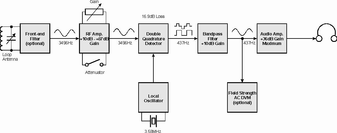
This receiver uses "double-quadrature" demodulation and re-modulation to down-convert a 3496Hz tone from the beacon transmitter (Pease, 1996a) to 437Hz. The design includes a signal strength meter and a facility to phase-lock the demodulator to the received signal. The D-Q receiver is essentially that of a narrow-band Turner/Weaver ssb demodulator. This article gives an overview of the device. Constructional details will be given elsewhere.
Introduction
The Beacon provides a continuous (non-pulsed) signal with a magnetic moment of about 19.8Am2. My goal was to create a very sensitive and selective receiver with good interference rejection plus the ability to measure signal strength, which would allow rapid depth estimates with a simple calculation.
To keep it simple (and cheap) the receiver was
designed
without transformers, inductors, filters, or tuned circuits other than
the loop antenna itself and an optional front-end filter for areas with
severe interference. It was built into an aluminium minibox using
generic
Radio Shack PC boards and draws about 19mA from a single 9V battery.
NOTE: The updated Receiver
uses a 12 V regulated supply and draws more current.
-------------------------
The Loop Antenna
In this receiver the thermal noise from the resonant loop limits the ultimate sensitivity. The antenna, veteran of other radios, is not an optimum design but does work well (Figure 1). The 18.25 inch diameter loop was wound with one pound of No. 29 enamelled wire (0.286mm diameter). It was wrapped with tape to keep the inductance stable. I got 430 turns; 234mH; Q=29. I added a (probably unnecessary) electrostatic shield which reduces Q to 25. It does seem to reduce "hand effects".NOTE: So far, my newest receiver loop seems to work fine without an electrostatic shield.
It resonates with about 7000pF giving an impedance of 125kW by itself. The loop is loosely coupled (470pF) to a second tuned circuit (which uses a 26mH toroid) to increase input selectivity but this extra filter is optional unless strong out of band interference is encountered. Both circuits are resonated using 1000pF Arco mica compression trimmers as part of the required capacitance. Everything is mounted on a rigid flat support along with horizontal and vertical bubble levels and fed with small coax (RG-178). NOTE: So far, my newest loop seems to work fine without the second tuned circuit.
Output impedance of the complete circuit is 215kW which gives a thermal noise of 59nV in a 1Hz bandwidth. The E-field "effective height" is 0.267 metres which makes the ultimate sensitivity of the loop, and the receiver, about 0.53 nA/m (equivalent noise H-field) at the 1Hz bandwidth.
The RF Amplifier
The RF amplifier is a straightforward 2-stage design using a cheap LF-353/TL-082 dual FET-input op-amp. Input impedance is 2MW . Gain can be varied from +10dB to +87dB. The circuit has low input noise (23nV/Hz measured) compared to the thermal noise of my loop. Combined noise of loop and receiver is about 63nV/Hz which makes the overall receiver sensitivity 1.3nA/m which is nearly as good as the loop alone. The receiver can make field strength measurements of the beacon signal from several hundred meters down to about 10 metres range.
NOTE: This amplifier has been updated to a 3-stage design with different op-amps to increase gain and improve linearity. See the construction article.
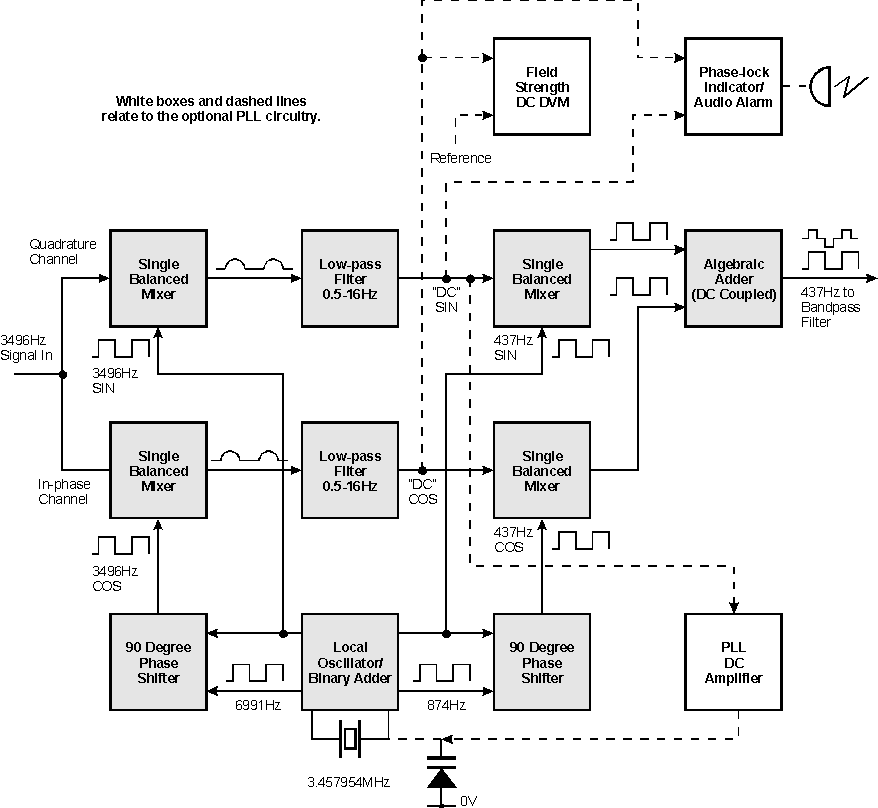
The Local Oscillator
The local oscillator, like the beacon transmitter, uses a common 3.579545MHz colour burst crystal which is binary divided to the 3495.65Hz carrier frequency (Figure 2). The local oscillator frequency is adjusted to match the beacon carrier to within about 0.05Hz. This turns out to be a stable setting that seldom (if ever) needs re-adjustment. Further frequency division creates the 437Hz audio tone. The 90 degree phase shift for each mixer pair is done with an exclusive-OR (XOR) gate which is driven at the fundamental frequency, f0, and at 2f0.
The Double Quadrature Detector
The RF amplifier output is DC coupled to the D-Q detector (Figure 2). This detector uses a 2-channel in-phase/quadrature direct-conversion mixer whose DC outputs are low pass filtered and then up-converted to a pair of audio tones whose algebraic sum is proportional to signal strength. The first stage, acting as a phase detector, produces DC voltages proportional to the sine and cosine of the 3496Hz signal. These baseband signals will slowly vary with time unless the receiver is phase-locked to the transmitter (phase-locking is an option which will be explained later). When one signal is zero the other will be maximum but their rms sum will always be proportional to the input signal. These signals are passed through 0.5 or 16Hz R-C low pass filters which defines the receiver bandwidth.
The great selectivity results from the fact that the 1Hz bandwidth mode rolls off at 20dB per decade based on the 0.5Hz -3dB bandwidth of the R-C filters. The response is -20dB only 6Hz either side of 3496Hz by actual measurement. Obviously the 32Hz mode is much poorer, but is only used with strong signals and for Morse Code at ground zero. More poles of filtering could be used but it doesn’t seem worth the effort.
I combined the signals by using a second in-phase/quadrature mixer to up-convert the baseband signals to 437Hz square waves with amplitudes proportional to the sine and cosine of the original signal which are then summed to produce a strange "shifting" waveform whose 437Hz fundamental frequency is exactly proportional to the original 3496Hz signal.
Note that the baseband signals cannot simply be summed and fed to an ordinary "true rms" DVM because a) "absolute value" circuits would be required for both signals before summing and b) most, if not all, of these meters are AC coupled for rms; also you would have no audio. A 1-stage op-amp bandpass filter recovers the sine wave whose strength can be measured by an inexpensive DVM set to AC volts. This signal is passed on to the audio amp.
Total "gain" through the D-Q detector and bandpass filter is about -7dB. Maximum linear output at the AC DVM is 0.5V RMS. Linear dynamic range of the receiver, measured at the AC DVM output in the 1Hz mode, is 69dB at full RF gain, 85dB at partial RF gain, and 140dB including the full range of the RF gain controls. One advantage of this detector is that the output remains a clean sine wave even when the receiver is seriously overloaded during the search for ground zero. A drawback is that it does not reject harmonics or sub-harmonics of the carrier frequency very well.
The Audio Amplifier
The audio amplifier is a conventional non-inverting op-amp designed for use with my 2000W high efficiency headphones (Figure 1). Its gain of 36dB is rolled off above and below 437Hz. For low impedance (8-30W ) "stereo" phones a more serious amplifier with up to 20dB more gain would be required, such as the LM-386. In the case of 8W phones I have found that an output transformer (1000 to 8W ) helps to prevent feedback problems and can be driven with a conventional op-amp if a second op-amp is wired as an inverter to form a "bridge" circuit.
NOTE: The construction article shows the LM-386 audio amplifier.
Operation
The receiver as described above works perfectly for locating "ground zero". The D-Q detector requires adjustments to null the 437Hz audio tone (another drawback) but it is usually easy to distinguish a real signal. As you get closer to ground zero the 32Hz bandwidth can be used to speed up the search since the 1Hz bandwidth causes unavoidable delays as the receiver "catches up" with each new position of the loop. If magnetic field shape is used to estimate depth then this is all you need for a receiver. I use the field strength at ground zero to estimate depth and I found that the AC DVM would fluctuate about 1dB as the beacon signal slowly drifted between the sine and cosine channels. This variation is inaudible in the headphones. No amount of "balancing" would make both channels exactly equal. The reading also fluctuated when the atmospheric noise was high. I concluded that I needed to phase-lock the crystal oscillator in the receiver to the one in the beacon if I wanted to make precise field strength measurements.
NOTE: A third "Ratiometric" method for measuring depth is described in the D-Q Receiver construction article.
The Phase-locked Loop
A PLL can easily be adapted to the D-Q detector to allow a DC DVM to be used for precise signal strength readings. "Absolute" and "Ratiometric" depth readings and conductivity measurements become possible. The baseband signal of one channel (now called the quadrature or sine channel) is connected to the input of a high gain DC coupled amplifier (+60dB) whose output drives a variable capacitance diode that can slightly shift the frequency of the 3.57MHz crystal. The total frequency shift (capture range) at 3496Hz is only 0.14Hz but my receiver has never needed frequency trimming after the initial adjustment. An R-C filter narrows the PLL bandwidth to 0.16Hz which allows it to lock on signals that are nearly inaudible in the 1Hz receiver bandwidth while ignoring power line harmonics. When locked, the baseband signal in the quadrature channel is held at nearly zero volts. The in-phase channel carries a steady DC voltage proportional to the beacon signal which is filtered further with an R-C network to 0.2Hz bandwidth for use when the receiver is not moving. Maximum linear output is about 0.65V DC.
A DC DVM works well here and takes about 10 seconds to reach a steady reading. Note that there is a 3dB improvement in the signal to noise ratio compared to the AC DVM (assuming 1Hz bandwidth for both) because the DC meter receives noise from only one channel. In reality, the DVM bandwidth is much less than 1 Hz resulting in further improvement. The AC DVM will still function, and no longer "drifts", but it still responds to the noise in both channels and its bandwidth cannot be easily narrowed. There is no change in the audio output when the receiver "locks" and "unlocks", so the PLL can remain "active" during the "search" even though it will break lock each time the beacon signal is nulled out. The audio signal to noise ratio could be enhanced 3dB (when phase-locked) by automatically disconnecting it from the Quadrature channel.
NOTE: The construction article shows the PLL as standard equipment. Optional circuits to allow use of an internal digital panel meter which shares the receiver batteries are also shown.
Lock Indicator and Alarm
To make waiting on the surface less boring I added a circuit to indicate when the receiver phase-locks on a beacon. It is just an op-amp integrator with a differential input that monitors the baseband (DC) output of both channels. When the in-phase channel rises a few millivolts (positive) above the quadrature channel and holds for several seconds then the integrator output will rise high enough to light the "Locked" LED. I added a loud audio alarm to alert (wake up) the surface operator who no longer has to listen to static continuously.
This is not a foolproof indicator since strong lightning strikes can trip it if the receiver gain is set too high, while it is possible for a signal below the threshold to phase lock especially if the gain is set too low! Also the threshold drifts somewhat with temperature such that it may give a lock indication without a signal at extreme temperatures. Voltage regulation and low drift op-amps would help. A steady (positive) reading on the DC DVM is a foolproof lock indication, but it is easier to just listen to the static than stare at the meter if you are this worried. In practice the alarm has worked fine in field tests.
NOTE: The construction article shows both a voltage regulator and low drift op-amps.
Field Trials
This receiver has been used to do numerous cave locations in New York State, Pennsylvania, South Dakota, and West Virginia with 100% success so far. I calibrated the receiver for amplitude using the beacon transmitter on the surface with both loops vertical and coaxial. The theoretical optimum range when used with my beacon (with a 2-foot loop) is over 800 meters (for coaxially oriented loops in "free space") with no power line or atmospheric noise, but real world noise plus the conductivity of the rock will reduce the useful range to a few hundred meters at best.
NOTE: In winter this range is greatly extended with a larger Beacon loop and with the receiver improvements described in the construction article.
The first location in West Virginia was a point far from the cave entrance on the other side of a hill. We made a really bad guess and found ourselves ¼ mile (400m) from ground zero when the alarm went off. We were on a steep hillside at about the same elevation as the beacon which did not help either. We finally had to walk along the "null" line for some distance, with the loop horizontal, while watching the signal strength indicator in order to figure out which way to go. We found lots of brambles and my wife found a large (but harmless) snake before we reached ground zero.
Fortunately we were able to keep in touch with the underground crew using 5W, 27MHz CB walkie-talkies, even from ¼ mile away, because ground zero was buried less than 10 metres deep in very dry limestone on a steep slope. I normally use an old 15kHz voice downlink I built years ago which has a jury-rig DSB transmitter on the surface with a small SSB receiver with a 6 inch (0.15m) ferrite rod antenna underground and just use CW on the Beacon for an uplink. Deeper locations also worked out well but without the two-way voice.
Changing to a Different Frequency
As mentioned in the beacon article, 3496Hz is not a good choice for areas with 50Hz power, such as the UK and other European countries.
A 3MHz crystal would give a 2930Hz carrier with the
nearest
harmonic 20Hz away. Other than the loop tuned circuits, the only
circuit
that would need to be changed is the 437Hz bandpass filter (to 366Hz).
A sharp cut-off low pass filter could be substituted to allow the
electronics
to work offer a range of frequencies.
The only changes needed to the
audio bandpass filters for 366 Hz operation are to change R15 and R45
(on the new boards with 2 filters) from 1.87k Ohms to 2.87K Ohms, 1%.
Construction
A construction article, including schematic, was written some time ago and should appear in the next issue of Speleonics (Pease, Unpublished). It appeared in Speleonics 21, March 1997, as well as CREG Journal 28.
Ian Drummond laid out a 3-part printed circuit board containing the beacon, receiver RF amplifier, and receiver which could be separated into 3 pieces before construction. These are double-sided with plated-through holes and include the PLL, lock indicator, and LM-386 audio amplifier circuits plus a small prototyping area. Four of these boards were etched by a commercial prototyper and are now in various stages of construction by Ian and 3 others (not me!) in the U.S.
When one of these PC-board receivers is completed and has been fully debugged I may offer some boards for sale. NOTE: 20 updated boards were made and sold during 1997. There are a total of 6 working receivers that I am aware of.
References
Pease, Brian (1996a) 3496Hz Beacon Transmitter & Loop, JCREG 23, pp22-24.
Pease, Brian (1997) The D-Q Beacon Receiver, Speleonics 21, pp10-19.
[Brian may be contacted at 567 Fire Street, Oakdale, CT 06370, USA – Ed]