The Simplest Radiolocator
Cave Radios for Everyone
Brian Pease
DEC 11, 2011
NOTE: This article
has/will appear in the CREG Journal and on the Speleonics
website in PDF form.
ABSTRACT
The Basic-1 Cave Radio addresses the need for a simple, short range, audio-frequency radiolocation and communication device that can be easily constructed, without test equipment, by anyone with basic soldering and wiring skills who has a rudimentary knowledge of electronics. It is really a throw-back to the original cave radios built and used in the 1960s, built as simple, light, and compact as possible. This article just describes the radios. Techniques for using them can be found at my website http://radiolocation.tripod.com .
Each Radio has the capability to act as either the surface receiver or as the underground beacon transmitter, which pulses 5 times per second. A good antenna is required to obtain useful performance from this simple circuit. A 48cm (19 inch) diameter circular loop with ~0.45kg (1lb) of wire serves as the antenna, parallel-tuned for receive and series-tuned for transmit. The simple 1750Hz circuit design uses a single 4-pin dual op-amp integrated circuit which acts as a preamp with 70 dB gain on receive, and as a free-running pulsed L-C oscillator on transmit with a magnetic moment of 1 Amp-turn-meter squared. 2-way CW (Morse Code) communication is possible between Radios. An optional built-in piezo sounder allows the underground unit to conduct transmitter monitoring and 2-way communications without bringing the large headphones underground. Older Amateur Radio operators have a real advantage here! Accurate ground zero locations are possible up to about 20 meters (67 ft) depths in ideal conditions, with 2-way communications theoretically possible to 60 meters (200 ft) depth if ground zero is already known. The Basic-1 is ideal for lava tubes and other relatively shallow caves, pinpointing where isolated passages intersect, and for locating new entrances where the depth is not great. The Basic-1 is powered by a single 9 Volt alkaline battery. The estimated battery life is 3 days of pulsing transmit operation, or 7 days of continuous receiving.
The Basic-2 design adds a second ~0.45kg (1 lb) of wire to the loop and a second dual op-amp, which increases location depth to 30 meters (100 feet) and 2-way communications to 90 meters (300 feet) depth in theory. The magnetic moment is 2.8 Amp-turn-meter squared. Battery life is half that of the Basic-1. Information on the availability of printed circuit boards, certain specialized parts, and nearly complete kits for both designs, including the special headphones, is on my website.
HISTORY
This author has had many requests over the years from cavers (and others) with a need for radiolocation gear for specific, often shallow, projects. The high power beacons and the super-sensitive “DQ” receiver designed by the author many years ago for long range use are overkill for their needs and much too complex for them to construct and operate (see http://Radiolocation.tripod.com).
The most recent request (for which I provided training and loaned my high power gear) prompted a literature search for a simple circuit seen decades ago. An excellent article in a 1984 issue of 73 Magazine by the late Frank Reid was my starting point 1. As seen in Figure 1, Frank showed what is likely the simplest cave radio possible. When I simulated this circuit in LT Spice, I found that it worked fairly well as a simple regenerative receiver, tuned to the audio frequency of the L-C tuned circuit. When the key is closed, it does oscillate, but the loop current is measured only in microamps, restricting the range to a couple of meters. Attempts to increase the transmitter output failed, resulting in a serious frequency shift.
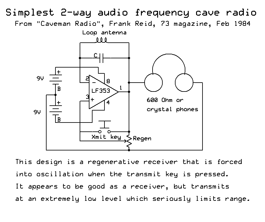
Figure 1
A series of experiments in Spice eventually evolved into the concepts shown in Figure 2. I chose essentially the same 48 cm (19 inch) diameter loop, with hundreds of turns, shown in Frank's article. The receiver is a classic non-inverting FET-input op-amp amplifier with high-impedance input and 70 dB gain. The parallel-tuned loop antenna consists of hundreds of turns of small wire, giving an impedance of ~23k Ohms and defines the receiver's bandwidth. This receiver has poor out of band rejection and suffers from some feedback between the dynamic headphones and the loop, but the simplicity is hard to beat.
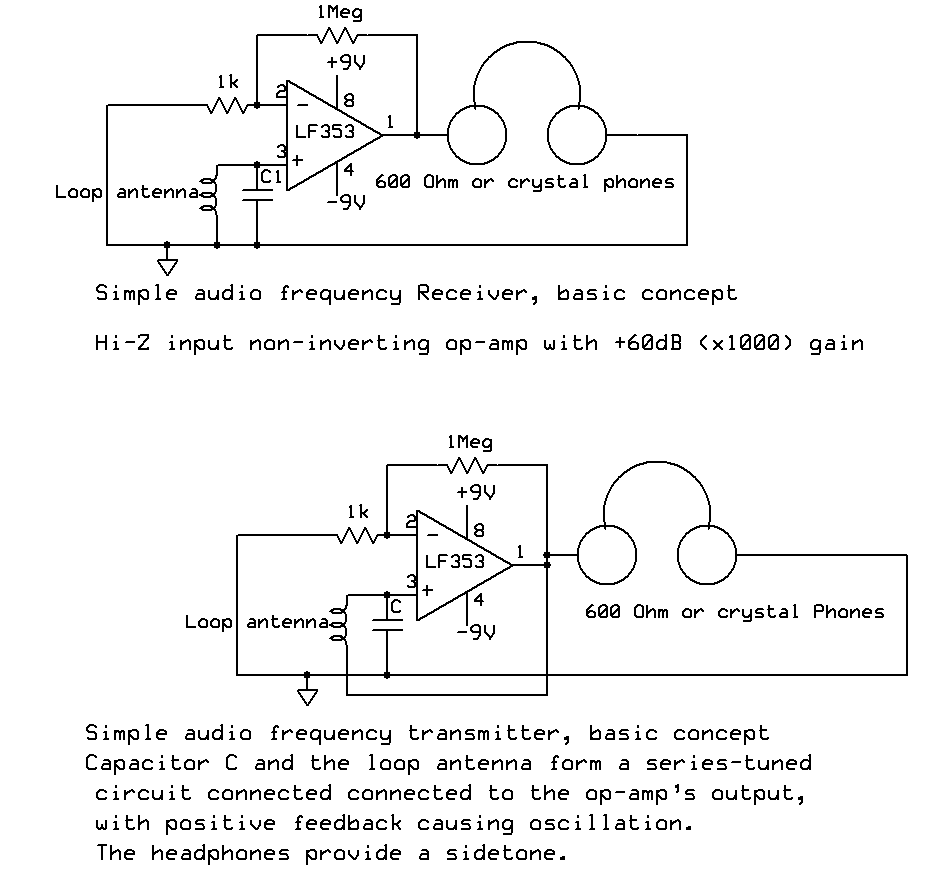
Figure 2
The circuit is turned into a transmitter by simply moving one end of the loop to the output of the op-amp, which will oscillate due to strong positive feedback. Since the loop is now series-tuned, the L and C reactances cancel, allowing the op-amp to drive significant current (tens of milliamps) through the resistance of the wire. There is some downward frequency shift when transmitting, compared to the center frequency of the receiver, which can be compensated for. All of the other components present in the final design are only included to improve the operation of this simple circuit.
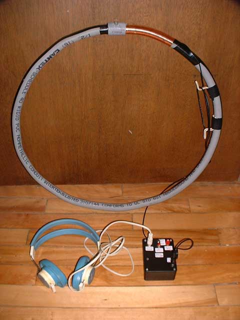
Figure 3
THE BASIC-1
This concept evolved into the Basic-1 cave radio pictured in Figure 3, with the circuit of Figure 4, which adds biasing to allow the use of a single 9 Volt battery; input protection for the op-amp; T/R switching, CW keying, and a beacon mode that pulses the transmitter at 5Hz. The 600 Ohm headphones are crudely resonated to their broad natural resonance at the operating frequency of 1750Hz. In addition to the tuned loop there are 3 low frequency roll-offs (4 if you count the loop) to help suppress 60Hz and its lower harmonics, plus a high frequency roll-off. There is a 1750 Hz sidetone for the CW and pulse modes, set to a reasonable volume that is independent of the receiver gain setting. The sidetone also acts as B.I.T.E. (Built In Test Equipment). You will not hear it unless the unit is actually transmitting. With the optional built-in piezo sounder, the underground unit does not need headphones for receiving or for the sidetone, making it very small and light. My desire to use a simple on-on-on 3-way toggle switch for the three modes (receive/CW transmit/pulse transmit) without added transistors or ICs resulted in some odd additions to the circuit. Appendix A gives the specifications and a detailed description of circuit functions. In ideal conditions, the Basic-1 can radiolocate a point to about 20 meters (67 ft) depth with reasonable accuracy, with the signal detectable about 45 meters (150 ft) along the surface from ground zero. This limits the usefulness to small or shallow caves although one could theoretically communicate 60 meters (200 ft) straight down in quiet conditions if ground zero was known in advance.
Figure 4
THE BASIC-2
I decided to try to improve the range of the Basic-1 without making it much more complex. The Basic-1 loop uses 0.4 kg (0.9 lb) of #28 enameled wire with 332 turns. For the Basic-2 I kept the 48 cm (19 inch) diameter but changed to 0.86 kg (1.9 lb) of larger #24 wire with 309 turns and a different resonating capacitor to maintain 1750 Hz. The Basic-2 loop had a much lower resistance (higher Q) which resulted in improved receiver gain and selectivity and (potentially) higher loop current in transmit. Because the Basic-1 circuit operates at the maximum current output of the single op-amp, I added a second IC with two additional identical op-amps in follower configuration in parallel with the original output (3 total) to boost potential output current x3 without other circuit changes, as shown in Figure 5. The simple DC connection with only 2.2 Ohm isolation resistors is possible because of the low (1 mv) laser-trimmed offset voltage of the LF412 op amp. This design boosted transmit loop current by nearly x3, increasing the beacon's output signal +9dB. The single 9V battery was retained.
Keeping in mind that the signal drops off as the cube of distance, the maximum depth increased to 30 meters (100 ft) with a horizontal distance of 70 meters (230 ft) from ground zero at this depth. Theoretical 2-way Communications depth at ground zero increased to 90 meters (300ft).
Figure 5
WHY HAVE 2 MODELS?
The primary reason for
retaining the Basic-1 is the very high
cost of copper wire, currently about $22.00 US/lb plus
shipping, and predicted to rise much higher. Just the wire
for a pair of Basic-2 loops is ~$100.00
US vs ~$50.00 for a Basic-1 pair. All of the
other parts are inexpensive.
NOTE: I have recently found cheaper wire in the
Industrial and Scientific section of Amazon, $17.00 for 1
lb of #28 and $16.00 for 1 lb of #26 with possible free
shipping. I have also seen 5 lbs of #24 on Ebay (buy it
now) for $68.21 with free shipping.
I have designed a PC board, using 100% thru-hole parts, that can be assembled to make either a Basic-1 or Basic-2 unit. Upgrading from a 1 to a 2 requires only changing 2 component values and adding 4 parts. The hard part is re-winding the loop, or building a new one.
If correctly built, a Basic-1 (with it's loop) can be used with a Basic-2 (with it's different loop) because they will both be operating on 1750 Hz.
CONSTRUCTION
I will be offering PC boards and also nearly complete kits, including a PC board (which will build either radio), case, all electronic parts, and Telex headphones at my cost on my website http://radiolocation.tripod.com . Not included is the loop form, enameled loop wire, and 9V battery. Assembly instructions, photos, board layout, operation, etc will be posted on the website. It should be possible to construct 2 loops in one day, and assemble 2 radios from kits in another day, making this a weekend project.
I am including enough information here for an
experienced builder to construct their own pair from scratch.
See my construction
article for details of building from a kit or just the
PC board, including printable PDF schematics, panel wiring,
etc.
First, refer to Appendix B and scrounge all of the parts for the version you wish to build. Remember to multiply the quantities by 2 for two units. If a circuit board is not purchased, then some proto-board with holes on a 2.5 mm (0.1”) grid should be purchased. I strongly recommend the expensive kind with plated-thru holes. My PC board is 1.25 x 2.5 inches (3.2 x 6.4 cm), but this is likely too small for hand wiring. The loop forms are builder's choice. Mine are formed from ½ inch ID (1.27 cm) gray PVC electrical conduit filled with sand then bent around a form (carefully) using a heat gun. A slot is then cut around the perimeter for winding. These are very light, can be transported over the shoulder, and don't blow around in the wind on the surface during searches. It is likely easiest to construct forms from stacked plywood disks. The core disk is 19.0 inches (48cm) diameter and ~½ inch (1.27cm) thick. The thin outer disks that hold the winding in place can be ~20 inches (50.8 cm) diameter. A similar form has been made (by a professional woodworker) by cutting a groove around a 20 inch disk of particle board ¾ inch (1.9 cm) thick. Note that the underground loop needs to have a circular bubble level attached to position it horizontally, and the surface loop needs an attached and carefully aligned level to precisely locate the vertical magnetic field at ground zero. See my website for details. Those with access to an LCR meter and an understanding of resonance can depart from the precise loop diameter, number of turns, and C1 values. Note that C1 should be low loss polypropylene, polystyrene, or mica, not Mylar, with at least a 50 volt rating (100 volts for the Basic-2). I would caution against changing the wire sizes or making the loops smaller in diameter, and would keep the operating frequency between about 1500 and 1900 Hz. Note that I have not tested frequencies other than 1750 Hz! The DC resistance of the loops needs to be similar to the standard loops, ~112 Ohms for the Basic-1 and 40 Ohms for the Basic-2. These values form the load seen by the op-amp (s). By matching loop inductance and capacitors (C1), it should be possible for 2 radios to operate within about 40 Hz of each other for the Basic-1 and 20 Hz for the Basic-2, which is desirable for the best performance. This can be checked by ear by transmitting with both units simultaneously while listening to one sidetone with each ear. The beat frequency that is the difference between the units will be obvious. The actual transmit frequency can be measured with a frequency counter or other instrument at TP1. Note the high open circuit voltage at TP1!
If building on a prototyping board, Keep the parts connected to the input pin 3 of U1A away from parts connected to pin 1. The REALLY critical thing is to make the lead connecting pin3 of U1A to R6, D2, D3, and C3 very short and well away from anything connected to pin 1. In Spice, it only took 0.3pf between pins 1 and 3 for the receiver to oscillate (at full gain). My prototype Basic-2 units did oscillate until I re-routed an output wire that passed near C3!
A plastic box works fine. If a metal box is used, it should be connected to battery negative, and both J1 and PH1 MUST be insulated from the box since neither is grounded.
Each group of 2 or 3 wires (the battery leads, headphone leads, CW key, SW1A, SW1B, R4) should be twisted together (in separate bundles) to cancel magnetic field radiation. The exception is the loop input to J1, which should be shielded cable, with the shield connected to pin 2 of SW1A. This is the square pad marked “S” on the PC board. The loop's feedline must also be shielded cable. I used RG-174 coax, but any shielded cable will do. Shielded twisted pair should also work, with the loop connected to the 2 wires and the shield connected only on one end to pin 2 of SW1A.
The LF353/TL082 op-amp will work in the Basic-1, but transmit output is slightly reduced compared to the LF412. If the LF353 is used in the Basic-2 (not recommended), R15-17 must be increased to 10 Ohms to account for the larger 5mv DC offsets.
The Basic-1 circuit should work without problems. Bringing the loop within about 2 feet of the headphones will cause the receiver to oscillate. Rotating either the headphones or the vertical loop 180 degrees may reduce the effect There is also some capacitive feedback through the operator's body because the loop is not shielded (which would reduce performance). Touching the bare wires on the headband of the earphones with ones hands may cause oscillation. In transmit (CW), there should be ~30V rms (AC) across the loop, with a nice sine waveform. This can be measured with any digital voltmeter (DVM), but the cheap ones may read somewhat low.
The Basic-2 is more prone to receiver oscillation because its higher-Q loop increases the receiver gain by ~9dB. See the website for instructions on adding a hand-ground to the loop. If the feedback is too annoying, change R1 from 330 Ohms to 1000 Ohms, which reduces the op-amp gain by 10dB. In transmit there should be ~60V rms across the loop.
1 Reid, Frank (Feb 1984) Caveman Radio 73 Magazine
http://www.scribd.com/doc/66643543/14005434-Caveman-Radio
APPENDIX A
Specifications and detailed circuit description
|
SPEC |
BASIC-1 |
BASIC-2 |
|
RECEIVER |
|
|
|
Input impedance |
1 Megohm |
1 Megohm |
|
Bandwidth (-3dB) |
130 Hz |
75 Hz |
|
Bandwidth (-30dB) |
670 – 6190 Hz |
975 – 3579 Hz |
|
Battery |
One 9V |
One 9V |
|
Battery current, receive mode |
3mA |
8mA |
|
Battery life |
~7 days |
~3 days |
|
Loop (48cm/19” dia) |
153mh, 332 turns #28 |
121.6mh, 309 turns #24 |
|
DC loop resistance |
~112 Ohms |
~40 Ohms |
|
Loop weight |
0.4kg (0.9 lbs) plus form |
0.9kg (1.9 lbs) plus form |
|
Radio weight, with battery, less headphones |
170 grams (6 oz) |
170 grams (6 oz) |
|
Parallel resonant loop impedance |
23k Ohms |
40k Ohms |
|
Headphones |
Telex 610 (600 Ohms) |
Telex 610 (600 Ohms) |
|
Receiver electronic gain |
+30 to +70dB adjustable |
+30 to +70dB adjustable |
|
TRANSMITTER |
|
|
|
Pulsing rate |
5Hz |
5Hz |
|
Magnetic Moment |
1 Amp-Turn-Mtr2 |
2.6 Amp-Turn-Mtr2 |
|
Battery current |
12mA key down, ~9mA pulse |
28mA key down, ~18mA pulse |
|
Transmit power (heat in loop) |
~40mW |
~90mW |
|
Battery life |
~3 days pulsing |
~1.5 days pulsing |
|
Loop voltage |
30V rms |
60V rms |
|
Loop current |
18mA rms |
45mA rms |
|
Maximum radiolocation depth* |
20 meters (67 ft) |
30 meters (100 ft) |
|
Max reception distance from ground zero at max depth* |
45 meters (150 ft) |
70 meters (230 ft) |
|
Max depth for 2-way comms* (estimated) |
60 meters (200 ft) |
90 meters (300 ft) |
* These estimates are for an experienced crew with little man made or atmospheric noise, fresh batteries, and typical limestone conductivity (not Florida or the tropics).
DETAILED CIRCUIT DESCRIPTION
Refer to the schematic (Figure 4)
Basic-1
Receive Mode:
Looking at the Basic-1 circuit of Figure 4, Loop L1 and C1 form a high-impedance parallel resonant circuit at 1750 Hz, which multiplies the received signal voltage by the “Q” of the circuit and also provides most of the receiver's selectivity. C3 and R6 aid selectivity by rolling off the response below 1750 Hz. R6 also provides 4.5V bias to U1 from the R3/R4/C4 divider. D2 and D3 protect the input of U1A, mainly during transmit. Op-amp U1A is wired as a high-gain non-inverting amplifier, with high input impedance, whose gain is [(R4 + R5)/R1] + 1. C2 provides a low frequency roll-off. At maximum gain, C5 rolls off the response above 1750 Hz. Diodes D7 – D14 are mainly for the transmitter, but also provide audio volume limiting for strong received signals. C6 roughly resonates the Telex 610 headphones at 1750 Hz, mainly providing another low frequency roll-off. PS1 (optional) acts as a built-in earphone and beacon monitor for underground use while R13 isolates the large capacitance of PS1 (.027uf) from the op-amp to prevent oscillation. Diode D5 grounds pin 6 of U1B in receive mode, forcing the output of U1B (pin 7) to +8 volts, which back-biases D1, allowing the receiver to operate. R7, R8, and all remaining parts (except the battery and reverse polarity protection diode D4) are used only for transmitting.
Transmit Modes
CW mode, key up:
C8 functions as a DC block allowing R7 and R8 to back-bias D5, which drops the output of U1B to 3 VDC (it is effectively just a voltage follower), causing D1 to conduct, which shuts down U1A to prevent transmission.
CW mode, key down:
The output of U1B is forced up to +8 volts, back-biasing D1 which turns on the amplifier U1A. Amplifier U1A's circuitry remains unchanged except that the “grounded” end of the loop has moved to the output (pin1) of U1A. This causes strong positive feedback at the positive input (pin 3) near the L1/C1 series resonant frequency (1750 Hz), causing the to circuit oscillate strongly at a very slightly lower frequency. C8 is placed in series with C1 to raise the transmit frequency ~25 Hz to match the loop's resonant frequency during receive. R14 allows direct measurement of the transmit frequency with a counter or oscilloscope. D2/D3 limit the input voltage to a 1V peak-peak square wave. Diodes D7 – D14 also conduct, effectively shorting out the gain pot R4 to eliminate variations in oscillation frequency or amplitude due to different gain settings. The output on pin 1 is ~6V p-p with the ~112 Ohm load of the series-resonant loop. This output is audible in the headphones and also in the optional piezo sounder. R7 and R8 attenuate this “sidetone” to a reasonable level. 18 mA rms is forced through the loop. As cave radios go, this is not much current, but it is circulating in more than 300 turns of wire. The strength of the transmitted magnetic field is determined by the Magnetic Moment, which is just the AC (rms) current flowing in the loop in Amps, multiplied by the number of turns and also multiplied by the area of the loop in meters squared.
Pulse mode:
D5 remains back-biased but R11 is now connected, providing positive feedback (hysteresis) to U1B, which begins to oscillate as a multivibrator at ~5Hz, producing a square wave output at pin 7 that causes D1 to turn U1A on and off at a 5Hz rate. This gives the same result as pressing the key 5 times/second in the CW mode. C7 and R12 set the rate, which is approximately 1/(C7*R12) Hz. Because R9 and R10 are not equal values, the “on” duty cycle of the transmitter is actually slightly less than 50%.
Basic-2
Refer to the schematic (Figure 5)
Receive Mode:
The receiver functions exactly the same as the Basic-1 except for a few extra dB of gain due to the reduced losses of the heavier loop. The second LF412, U2, does nothing to aid reception. C1 is a different value to resonate the different inductance of the Basic-2 loop to 1750 Hz.
Transmit Modes:
Both modes function
exactly the same as the Basic-1 except that U2
provides a big current boost to the square wave output to
enable it to drive the 40 Ohm series-resonant load of the Basic-2 loop. U2A and U2B
are connected as unity gain followers with their outputs in
parallel with U1A. Resistors R15-17 isolate the 3 outputs
from each other (and from pin 1) while introducing
negligible loss. The low value of 2.2 Ohms is possible
because the LF412's are laser trimmed for a DC offset (input
to output) of <1mV and because the gain is so close to
unity. The use of LF353's would require 10 Ohm resistors for
R15-17. The three op-amps in parallel have 3 times the
output current capability of U1A alone, forcing 45mA through
the loop (and 60 V rms across it!). There are only 2 other
minor circuit changes. One is C8, whose value is lowered
from 4.7uf to 3.3uf to raise the transmit frequency slightly
more than the Basic-1. The other is the
addition of D6 and D15 in series with D5 to prevent
conduction during transmit with the more robust output
waveform, which would lock the transmitter “on” and prevent
the 5Hz pulsing in the beacon mode.
APPENDIX B
|
|
|
PARTS FOR A SINGLE BASIC-1 UNIT |
*See bottom for Basic-2 |
parts |
|
ITEM |
QTY |
DESCRIPTION |
PART # or SOURCE |
COST |
|
B1 |
1 |
Standard 9V battery |
Local |
----- |
|
*C1A,B |
2 |
.027uf, 3%, 800Vpolypropylene cap |
P14260-ND |
$0.82 |
|
C2 |
1 |
1uf 50V X7R ceramic |
DigiKey 478-4657-ND |
$0.86 |
|
C3 |
1 |
330pf 100V NPO ceramic |
399-4173-ND |
$0.40 |
|
C4 |
1 |
1uf 35V tantalum (16V ok) |
478-5812-ND |
$0.40 |
|
C5 |
1 |
47pf 50V NPO ceramic |
399-4181-ND |
$0.43 |
|
C6 |
1 |
0.1uf 50V ceramic |
478-3188-ND |
$0.24 |
|
C7 |
1 |
0.22uf 50V ceramic |
399-4288-ND |
$0.65 |
|
*C8 |
1 |
4.7uf 16V tant |
718-1220-ND |
$0.86 |
|
D1-3,5,7-14 |
12 |
1N914/1N4148 silicon signal diode |
RS 276-1620 |
$2.99/50 |
|
D4 |
1 |
1N4001power diode (or similar) |
RS 276-1653 |
$2.99/25 |
|
*L1 |
~0.9 lb |
332 turns #28 enamel 19.0” dia, ~1750 ft |
Tech-Fixx, Ebay |
$21.60/lb |
|
PH1 |
1 |
Telex 610 series 600 Ohm mono phones |
I hasve these for sale |
$4.00 |
|
PS1 |
1 |
Piezo speaker (optional) |
RS 273-073 |
$2.19 |
|
R4 |
1 |
1Meg audio taper mini pot with switch |
CT2222-ND |
$3.85 |
|
R1 |
1 |
330 Ohm ¼ W 5% carbon comp resistor |
RS 271-312 |
$9.99/500 |
|
R2,3,9 |
3 |
100K “ “ |
All resistors are in |
|
|
R5, R7 |
2 |
10k “ “ |
The 500 piece |
|
|
R6,12,14 |
3 |
1Meg “ “ |
Radio Shack |
|
|
R8 |
1 |
47 Ohm “ “ |
assortment |
----- |
|
R10 |
1 |
82k “ “ |
(or DigiKey or Mouser) |
|
|
R11 |
1 |
150k “ “ |
One value $0.06 ea |
|
|
R13 |
1 |
1k |
In qty 10 at DigiKey |
|
|
R15-17 |
3 |
2.2 Ohm “ “ |
|
|
|
SW1 |
1 |
3-way on-on-on mini toggle switch |
Ebay (my qty purchase) |
$1.00 |
|
SW2 |
0 |
Part of R4 |
--------- |
------ |
|
SW3 |
1 |
Momentary push button, norm open |
M.P.Jones 5019-SW |
$0.29 |
|
U1 |
1 |
LF353 or TL082 dual BiFET op-amp (LF412 is better and recommended) |
RS 276-1715 296-7141-5-ND |
$2.19 $0.76 |
|
L1 plug |
1 |
RCA phono plug with cable clamp |
RS 274-451 |
$3.99/6 |
|
L1 jack |
1 |
RCA phono jack with threaded mount |
RS 274-346 MPJA 5522-PL |
$4.19/4 $0.34 |
|
PH1 jack |
1 |
1/4” or 1/8” to fit phones (no switch) |
RS 274-252 or 274-0248 |
Local |
|
*DIPsocket |
1 |
8 pin DIP socket |
RS 276-1995 A100204-ND |
$0.59 $0.12 |
|
PC board |
1 |
Standard service incl shipping |
ExpressPCB |
$4.25 |
|
Box |
1 |
Plastic box, screw-on lid, 3x4x1.5” high |
M. P. Jones 15523-BX |
$2.49 |
|
B1 holder |
1 |
Snap-in 9V battery holder with 6” leads (tape mounted) |
BH9VW-ND |
$1.30 |
|
Tape |
2” |
Double-sided sticky tape for Bat holder and optional piezo speaker |
Local |
----- |
|
Knob |
1 |
Volume control Knob (R4 has 1/8” shaft) |
See notes below |
----- |
|
Coax |
5.5 ft |
5 ft RG-174 feedline for loop plus 6” for PC board wiring |
Ebay |
----- |
|
Wire |
6 ft |
#26 hookup wire PC board 2 ft of 3 colors |
Local |
----- |
|
Hardware |
2 sets |
4-40 x 1/2” FH screw/nut/spacer 1/8” spacer cut from plastic tubing |
Local |
----- |
|
Hand gnd |
2 ft |
1” wide copper foil |
I have a supply (SASE) |
----- |
|
Tape |
|
Vinyl electrical tape for loop (if needed) |
Local |
----- |
|
Shrink tube |
|
Small tube, loop wire splices (if needed) |
Local |
----- |
|
Circ level |
1 |
Circular surface level for cave loop |
Local |
----- |
|
Line level |
1 |
Line or RV level for surface loop |
Local |
----- |
|
ITEM |
QTY |
ADDED OR CHANGED PART |
PART # or SOURCE |
COST |
|
C1 |
1 |
Replace(2).027uf with(1).068uf 3% 400V |
P12083-ND |
$1.68 |
|
C8 |
1 |
Replace 4.7uf 16V tantalum with 3.3uF |
718-1217-ND |
$0.76 |
|
D6, D15 |
2 |
1N914/1N4148 |
See D1 |
|
|
L1 |
~1.9lbs |
309 turns #24 enamel 19” dia, ~1545 ft Replaces the 0.9 lb #28 Basic-1 loop |
Same sources |
Similar/lb |
|
R15-17 |
3 |
2.2 Ohm ¼ Watt carbon film resistor |
RS assortment |
|
|
U1,U2 |
2 |
Must be LF412 for Basic-2 due to high output and low DC offset (see text) |
296-7141-ND |
$0.76 |
|
DIP socket |
1 |
A 2nd 8-pin DIP socket is required |
|
|
Notes: Most of the Radio Shack parts are available from the other suppliers. Mouser.com is another good supplier. DigiKey has other choices for most of the part numbers shown.
Radioshack.com (RS parts)
digikey.com (ND parts)
mpja.com (M.P.Jones parts)
For knobs for 1/4” shafts go to Radio Shack. For 1/8” shafts try allelectronics.com KNB-127 for $1.27 ea, or surplussales.com (KNB)PKG50B1/8 or (KNB)RN-99F1 for $2.00 ea.
M.P. Jones has the 4 ceramic capacitors very cheap.
I have some non-adhesive 1” wide copper foil for shielding for free. Send SASE.
I have the Telex 610 Headphones for $4.00 plus shipping.
The circular level is a standard item available in most hardware stores. The line level (designed for hanging on a string) is available at Home Depot. The 3/8” dia cartridge snaps out of the holder. Smaller stick-on levels can be found at an RV/trailer dealer, used to level trailers.
Color codes for the brown 5% carbon film resistors. There are 4 color bands with the last band being gold, which indicates 5% tolerance. 1% resistors are blue and have 5 color bands. A quick Ohms check with a cheap Digital Voltmeter is a good idea. Sears often has a good meter on sale for $10.00, Harbor freight for $5.00.
|
Resistor |
Value (Ohms) |
Color Code |
|
R1 |
330 |
Orange, orange, brown, gold |
|
R2,3,9 |
100k |
Brown, black, yellow, gold |
|
R5 |
10k |
Brown, black, orange, gold |
|
R6,12,14 |
1Meg |
Brown, black, green, gold |
|
R7 |
4.7k |
Yellow, violet, red, gold |
|
R8 |
47 |
Yellow, violet, black, gold |
|
R10 |
82k |
Gray, Red, Orange, Gold |
|
R11 |
150k |
Brown, green, yellow, gold |
|
R13 |
1k |
Brown, black, red |
|
R15-17 |
2.2 |
Red, red, gold, gold |
NOTE: The oriental perception of colors, especially brown and violet, red and orange seems to be different from mine. I often have trouble distinguishing between them unless they are side by side.