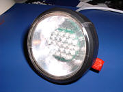
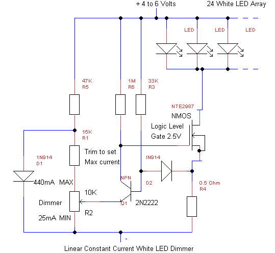
DIMMER FOR A WHITE 24-LED ARRAY
This simple Linear circuit provides continuously variable regulated current (~25-400mA) from a 4-6 Volt source. I chose a linear design for simplicity, reliability, ease of repair, and to avoid switching EMI in my Cave Radios. The circuit requires only 0.2V headroom above the parallel LED Array voltage to provide regulation at maximum current. The headroom stays low until the LED's are extinguished at about 0.75V/cell for 4-cell packs. End of life for alkalines is usually considered to be 0.9V/cell. My HDS 24-LED array requires 2.9V at 25mA and 3.5V at 440mA. The circuit can be scaled for larger or smaller arrays, and should actually handle several Amps with a larger heatsink. With 4 AA Alkalines, life should be 3 hours (or more) at maximum setting for a 24-LED array, but ~60-80 hours at minimum setting, which is bright enough for many activities, including reading, if the mounting bracket allows the lamp to pivot downward like mine does. In a two week test, I found that the white even light made caving easy. The "rings" and sharp cutoff of halogen lamps are absent. I found that I could usually get away with 200mA when moving, and much less when stationary (surveying, resting, eating), getting up to a10 hour trip from 4 AA's. The real beauty of white LED's is that the light remains white even at the lowest settings, compared to halogen light which shifts rapidly to infrared when dimmed.
The battery pack can be 4 AA, C, or D size Alkaline, Ni-Cad, NiMH, 1.5V AA Lithium cells, or a 6V Lead-Acid. 3-cell C or D Alkaline packs should also work, but they will not be discharged as deeply. "Dead" cells from Halogen lamps, GPS, etc., should give hours of "free" light at lower current settings. My latest pack is two 3V, 8AH lithium cells removed from a military surplus BA-5598/U battery (5 cells/battery). These are available from Fair Radio Sales at http://www.fairradio.com at 2 for $6.50 plus shipping.
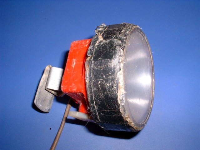
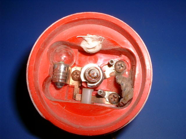
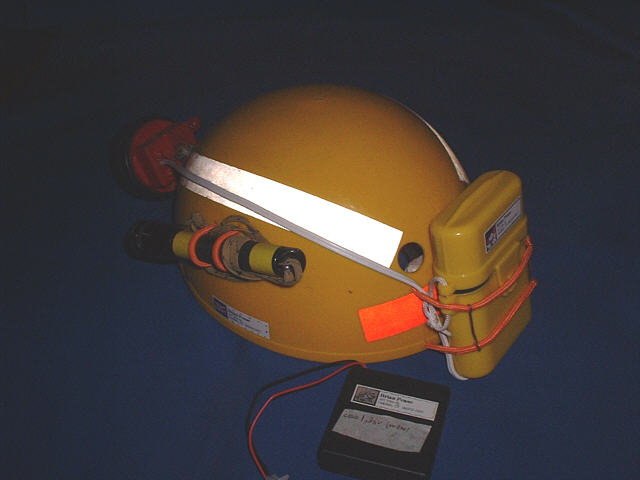
My headpiece is an old waterproof "Easter Seals"
Lexan "Roosa" light with a rocker on-off switch. See http://www.lightingpro.org
(under
construction), but you can call them directly (860-728-1061 in CT) or
email
sales@lightingpro.org. The red model HL-4AA with a 4AA pack on
its
headband is $20. All the parts are available separately, including the
headpiece, battery packs, and replacement lenses. They also sell
a complete headlamp with halogen bulb (and spare) with Willy Hunt's
microtroller
switching voltage regulator (not suitable for LED's) for $55 retail,
but
maybe at $45 if you are worthy.
Because I am lazy, I purchased a 24-LED parallel
array from Henry Schneiker of HDS systems at http://www.hdssystems.com
or 1-877-437-7978 (toll free). If you are a caver, he might be willing
to sell you enough LEDs for a light at reasonable cost, but remember
that
they must be matched for this parallel array. The Nichia LED's have a
20
degree half power beamwidth with significant sidelight, which seems
ideal.
The simplest and surest way to get premium Nichia LEDs is to order
directly
from http://www.nichia.com .
The part number is NSPW500BS (20 degree, 6800 mcd, 5 mm dia,
flange).
The cost is $2.05 each for a quantity of exactly 100, plus $8.00 for
prompt
shipping. Smaller quantities are way too expensive, and you need to
sort
them by voltage drop (at 20 mA) from a larger batch anyway.
See Garry Petrie's "Perfect LED Light" at http://home.europa.com/~gp/perfect_led_light.htm
for detailed technical info on white LED's and a simple way to assemble
an LED array on a do-it-yourself circuit board. He shows how to
install
arrays into Petzl Micro and Mega headlamps using switching regulators.
However, the regulators themselves are constant voltage rather than the
desired constant current, and are the lamps truly submersible? An
excellent
Website. Another resource is the LED Flashlight Page, http://www.uwgb.edu/nevermab/led.htm.
See Ray Cole's Website, http://members.cox.net/k4gaa/caving.htm,
for info on a 24 LED light using a series-parallel arrangement to
nearly
eliminate matching, and an efficient dimmable switching regulator.
I used a commercial array
because
of the careful voltage matching required in order to obtain anywhere
near
equal light from each LED when they are wired in parallel (and avoid
overheating
at full power). I would have to had purchase a large quantity of LED's
to solve this problem. This was expensive, but was the only real cost.
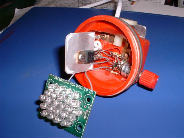
The MOSFET current source
can be any N-channel enhancement mode unit designed to be driven by
"logic
level" signals. It must fully turn on at 400mA with Vgs<3V.
Beware
of static electricity on the gate of this unit! I destroyed the IRLZ34N
used in the breadboard when I soldered it into the actual unit. A small
1" square of sheet aluminum serves as a heat sink. Dissipation is about
0.9 watts at maximum current with a true 6V worst case source.
R4 samples the LED current.
Voltage drop is 0.2V at 400mA. If a much larger or smaller array is
used,
R4 should be adjusted to give ~0.2V drop at maximum array current
(~20mA/LED).
Q1, D2, R3, and R6 form a
simple "single supply" op-amp that can sense the voltage across R4
nearly
down to zero volts. The forward voltage drop across D2 is nearly
identical to the base-emitter drop of Q1, thus the voltage between the
arm of R2 and ground is the same as the voltage across R2. D2
provides
nearly perfect temperature compensation for the dimmer control, which
becomes
very critical at the dimmest settings.
R5, and D1 provide a regulated
voltage for the dimmer control R2. This voltage, about 0.5V, is
not
temperature compensated, but is not critical in this design.
If R2 is set to max current,
0.2V will appear on the base of Q1. The collector current of Q1
will
be momentarily be cut off, which will turn on the MOSFET. The
voltage
across R4 will rise until it reaches 0.2V, giving an array current of
400mA.
Q1 will then turn on, regulating the array current.
R1 is the only critical
part.
R1 must be chosen to provide the desired maximum array current at the
maximum
setting of R2.
The drop across the LED array
is ~3.5V at maximum current. As the batteries die, the drain-source
voltage
of the MOSFET gradually drops to zero, and regulation is lost. The lamp
will gradually dim, but the MOSFET will stay locked ON, with the only
wasted
power being the drop across R4. Dimming the lamp will bring it back
into
regulated
mode for a while. This circuit extracts nearly all of the energy in the
battery pack, down to 0.75V/cell for a 4-cell pack.
The ~25mA minimum array
current
results from slight differences in the forward voltage drops of D2 and
Q1. If desired, replacing D2 with the base-emitter junction of a second
2N2222 should reduce the minimum current to ~zero.
There are variations of this
circuit such as one by my namesake Bob Pease in the Sept 5, 2000 issue
of
Electronic Design Magazine
using
a voltage regulator and a BJT. Another variation uses a real low
voltage
single-supply op-amp in place of Q1 and either a BJT or MOSFET.
|
USING THIS REGULATOR WITH HIGHER
CURRENT ARRAYS, SUCH AS LUXEON LEDs
This circuit
should work well as-is with a 1 -Watt Luxeon LED, but it has not been
tested.
If you wish to experiment with higher current arrays, such as a 4-Watt Luxeon LED (which I don't really recommend), proceed as follows:
|
First,I
breadboarded the entire circuit in order to test the design and set the
maximum current limit.
Next, I "hogged out" the
interior
recess of the Lexan Easter Seals headpiece with a Dremel Tool, and also
removed uneeded metal from the switch contacts. The 1/2" dia pot
was positioned as far to the rear as possible so that the knob (1/8"
shaft)
would clear the lens when the lens was screwed on. Point-to-point
wiring was used for the regulator, without a circuit board. Everything
was installed as far to the rear as possible to allow the TO-220 MOSFET
to fit over the circuit with a flat aluminum heat sink cut to fit into
the recess. Stranded hookup wire was used to make the 3 connections to
the MOSFET. Spacers of Index card paper were used above and below
the MOSFET to prevent shorts. The LED array sat on top of the recess,
resting
on its 4 corners. A large hole was cut in the plastic reflector,
by slicing off the back, to clear the LED's on the arrays' circuit
board.
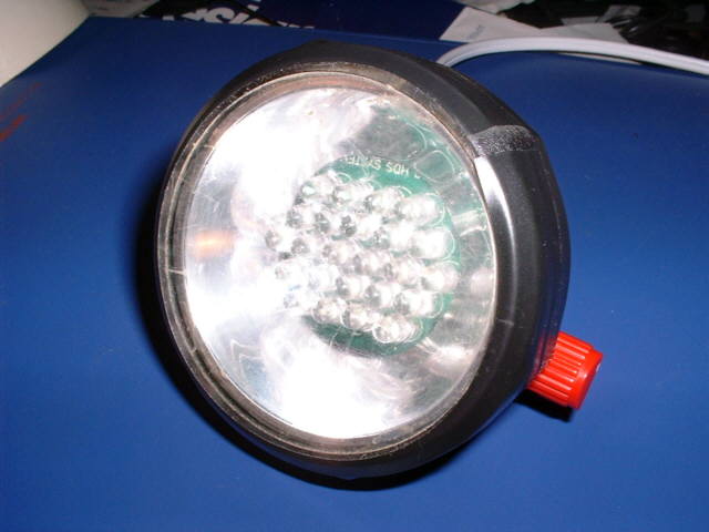
The main purpose of the reflector is to hold the LED array firmly in
place
when the clear lens is screwed on, but it actually does direct a little
light forward and besides, it looks cool. Black electrical tape
was
wrapped around the flange of the lens to keep direct light out of the
users
eyes. Calibration marks were melted into the housing to calibrate the
dimmer
knob every 100mA (1,2,3,4).
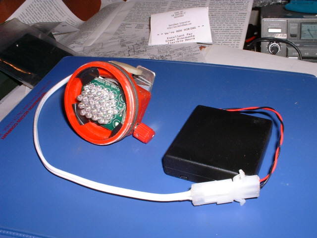
Water must be kept off the circuit. Specifically,
water on the high-impedance MOSFET gate line will cause the array to go
dim until the circuit is dried out. I used silicone rubber over all the
wiring. I installed a $1.00 watertight swimmer's "dry" container on my
helmet to hold the Radio Shack 270-409 battery pack. There is also room
for 4 spare AA cells, although I simply bought 2 spare packs at $1.50
each
and installed $.99 Molex connector pairs (274-222) which also allow use
of the original Easter Seals Lexan belt-clip battery case, which holds
4 Ni-cad 4-AH D cells soldered together for a really long trip.
For long-life expedition use, I recently
constructed
a waterproof cylindrical pack to hold 2 of the surplus 8AH lithium
cells
mentioned earlier. The pack, pictured here,
is simply a short piece of "1.5 inch" PVC pipe with a glued-on end cap
on the top, and a clamp-on rubber cap on the bottom.The two separate
wires
exit the rubber cap thru very small drilled holes which eliminates the
need for any special sealing arrangement