3496 Hz Beacon Receiver
|
|
For three months during the
winter of 1998/99, the US Deep Caving Team (a non-profit group) led the
Wakulla
II dive expedition to Wakulla Springs State Park, which is located
on the Woodville Karst Plain in northern Florida just south of Tallahassee.
Earlier work by Bill Stone, and more recently by the Woodville Karst Plain
Project, resulted in a map of much of the Spring, but the only published
passage details are found in Bill's book on his 1987 Expedition.
A total of about 150 divers and support personnel were involved for all
or part of the time. The purpose Of this Expedition was to create a Precise
3-dimensional map of the extensive underwater cave system feeding the Spring
which will allow Park visitors to see more than just the huge entrance
in the spring pool. Most of these large passages are 300 feet
(90 meters) below the surface (and nearly 300 feet underwater), and require
world class diving to visit. Eventually, it will be possible for
Park visitors to "fly" thru the passages (and over the surface features)
in a manner similar to a video game. To accomplish this task, a formidable
device called the Digital Wall Mapper was designed
and built to collect the data. The Wall Mapper attaches to the front
of a long range battery-powered "scooter" which is "flown" thru the passages
by a diver . The resulting assembly is nearly as large as a torpedo.
This device contains a sonar array which creates 4 crossectional "images"
each second. A modified Inertial Guidance System from an aircraft
gives roll, pitch, yaw, true heading, and "X" and "Y" positions. The "Z"
position (depth) is obtained from depth sensors. The data is downloaded
from the Wall Mapper with a laptop PC and transferred to a powerful graphics
work station. Complex software was written to create a 3-dimensional
image of the cave passages from the raw data. The resulting crossections
are very accurate, but the track created by the Inertial Navigator (equivalent
to the line plotted with compass, inclinometer, and tape, in dry cave surveying)
contains random errors that increase with time (i.e. inertial drift).
Inertial Navigators use a gyroscopic-stablized platform with x, y, and
z sensors that detect acceleration. At the start of each run, the
platform is told where it is located (x, y, z). Velocity and position
can be calculated from the acceleration data, but even small acceleration
errors will result in large position errors after a few minutes.
Other than frequent resetting of the Inertial Navigator (which
could be done by the diver) the best solution to the drift problem was
to place markers throughout the cave, whose location on the surface was
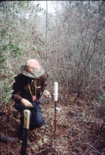
determined by the use of so-called "Cave Radio". Low
Frequency Magnetic Induction Beacons placed in the cave during exploration
were precisely located on the surface using special receivers. These new
points were tied into the growing cave map initially by Coast Guard DGPS
followed (when time allowed) by a combination of Survey-grade GPS and precise
overland survey back to a reference marker at the Spring Pool. The diver
pressed a button as the Wall Mapper "flew" over each marker which tied
the downloaded data to these precise points.
|
|
|
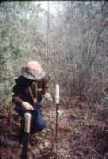
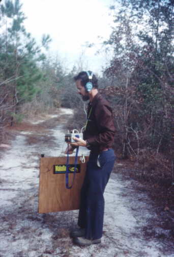
3496 Hz Beacon Receiver |
The Beacon Receiver is crystal controlled and uses a high gain "double-quadrature" two-channel in-phase/quadrature (I/Q) design with a 1 Hz bandwidth. The Receiver phase-locks on the Beacon signal, which allows a digital readout of signal strength. Relative gain of the receiver is precisely calibrated. A 22 inch tuned loop antenna with a bubble level is used for searching. While rotating the loop, sharp nulls in the signal give the direction to "Ground Zero". See Cave Radio Basics for a description of how magnetic induction radio works, along with a little geophysics. See my Website for more theory, schematics, construction, etc. |
|
|
|
Signals can be good in the woods |
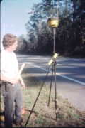
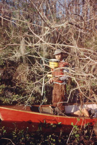
DGPS gear was used to give a rough fix (~4 mtrs) immediately after each Underwater Beacon was located and was used as a reality check for the precision surveying done later. Selective Availibilities 50mtr+ error with a "bare" GPS receiver was considered not acceptable. This gear consisted of a GPS-45 single channel GPS receiver with a LOWE active patch antenna elevated on a one square foot ground plane with an Eagle 300kHz "all-in-one" Differential beacon receiver with 4 foot whip and a 12V gel cell to power it all. Several hundred track points were recorded at each location which were later downloaded using Waypoint+ and visually averaged if the plot looked good. |
DGPS Beacon Receiver in the Field |
|
|
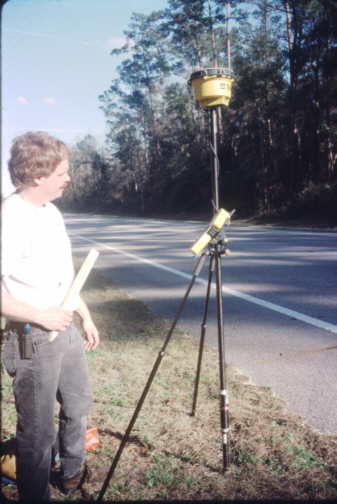
Trimble Receiver and Data Logger creating a point for the total station |
Midway thru the expedition we were loaned a complete Trimble 4800 Real-Time-Kinetic Phase Differential GPS System with a reference receiver (with radio link) at the spring pool located to <1cm. The Trimble gear eventually directly located every point outside the park (and many within) to within 1cm. Where the old growth forest canopy prevented a precision fix directly at a "Ground Zero" location, two precision points were marked in the nearest open area for later use by convention land survey gear. A wonderful timesaver! |
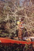
Centimeter accuracy here? YES! |
|
|
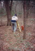
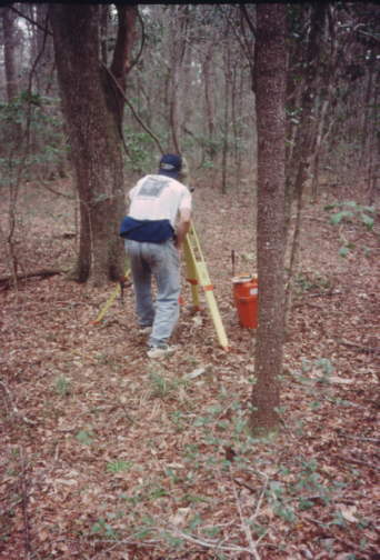
Bill Stone surveying along a cleared pathway |
Conventional surveying was used near the end of the expedition for "mop up". This included points in the deep forest within Wakulla State Park where the Trimble could not receive enough satellites or experienced too much multipath. There were also points in deep water where it was easier (and less risky) to deal with just a retroflector in the canoe. Unlike the Trimble GPS, which could be operated by one person, 3 people (and 2-way radios) were needed for the surveying, plus a lot of preparation in advance including setting up pairs of reference points with the Trimble and clearing long sight lines with a machette. The Leica did allow us to locate these remaining points to within 1cm. |
FOR MORE DETAILS
|
|
|
|
|
|
|
|