Constructing the Basic-1 and Basic-2 Radiolocation/communicators from kits
This document describes the construction of the
Basic radiolocation units from kits,
but can also be followed by someone who has purchased only a PC
board and gathered the parts themselves using the parts list.
This is written assuming that a caver in the US has purchased
the kit (only US measurements are shown), which includes
everything except the battery, the loop wire and form, and the
optional piezo sounder.
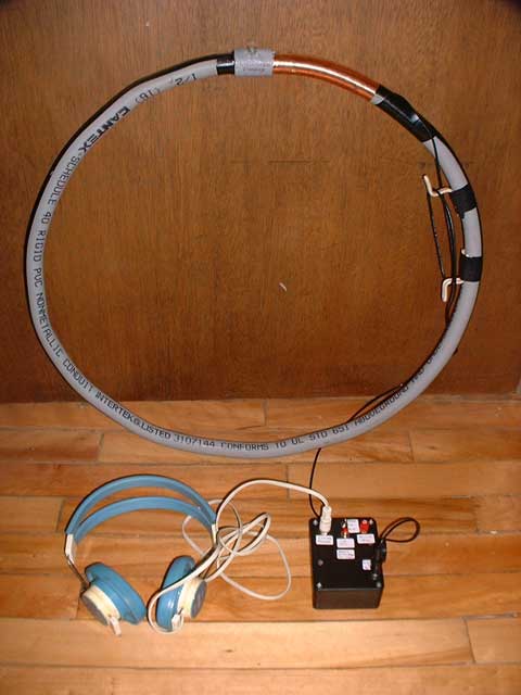
Figure 1
LOOP
First the hard part – the loop! Order 1 lb of #28 enameled wire for each Basic-1 radio kit or 2 lbs of #24 enameled wire for each Basic-2 radio kit. My most recent source was Tech-Fixx on Ebay. The loop form must be constructed and, depending on your skills and the construction method chosen, may be the hardest part of the project.
If you are lucky enough to find a pair of used plastic bicycle or wheelchair wheels of about the right diameter, let me know the exact diameter of the bottom of the “trough” where the tire went. I can calculate the correct number of turns.
I wanted the lightest most portable loops possible for personal use. I own a cheap heat gun, from Harbor Freight, which can blow air up to 1000 degrees F. I purchased some gray PVC electrical conduit with ½ inch ID and a coupler that is used to join (glue) 2 pieces together. 19” diameter is 5.0 ft perimeter, so I cut a 5 ft length and formed it into a 19” circle with the heat gun. See Figure 1. This is easier said than done! First I cut 2 plugs for the ends of the conduit; ½ inch wood dowel several inches long will do. I then taped a plug in one end (leaving several inches sticking out), filled the conduit with dry sand, then plugged the other end. This prevented kinking or flattening when the heated plastic was bent. I then duct-taped one plug to the rim of a small metal garbage can lid, which acted as a form. My lid was 17” diameter, a bit small. The large beaded rim helped keep the loop straight as it was bent. Donning oven mitts, and with the heat gun on its low heat setting, I then carefully heated the first few inches of the conduit, then gently bent it around the lid, continuing around in increments. It was difficult to make a perfect flat circle, but my loops look OK. It is more important to be flat than perfectly round. Next I emptied out the sand. The coupler was then used to glue the ends together. I then cut a slot around the outer perimeter ~0.1” wide for winding. I used a table saw with a cheap plywood blade, with hundreds of teeth, installed backwards so the teeth would not catch. Similar results could be had with a router or a hand saw. The resulting form weighs only a few ounces, gives complete protection to the wire, requires no handle to carry or use, and can be carried over a shoulder while walking.
Probably the quickest and easiest (but heaviest) way to construct a loop is to start by cutting a 19.0” diameter circle of ½ inch thick plywood plus 2 larger circles of thin plywood 20 or 21 inches diameter. These are stacked with the 19” disk in the middle to form a winding slot around the rim. The loop should be assembled with glue and/or fasteners tightly such that windings cannot slip between the layers of plywood. Prior to assembly, the center of the loop can be lightened, a recess added to protect a bubble level for the underground loop, etc. It is a good idea to add a flexible handle with cords and a piece of dowel for carrying and to allow the loop to hang perfectly vertical while searching on the surface.
Next wind the loop with 332 turns of #28 for a Basic-1 loop or 309 turns of #24 for the Basic-2. Keep some tension on the wire. I find it best to count to 10, mark, count to 10, mark, etc when doing this many turns. Cut 5 ft of RG-174 coax. Assemble the RCA phono plug on the coax, soldering the shield. Use long nose pliers on the shield as a heat sink to prevent melting the center dielectric. This shield should be tinned with solder before assembly, which may be a bit difficult, but be patient. Carefully crimp the cable clamp, then slip on the cover. Solder the cable to the loop and provide a strain relief with tape around the PVC form, or a clamp on the wood form. If you have a DVM, check the resistance across the phono plug, which should be approximately 112 Ohms for the Basic-1 loop and 40 Ohms for the Basic-2. Both of your loops should have the same resistance. This test pretty much assures that the loops will work. Especially on the plastic conduit loops, I would consider adding the copper foil “hand ground”. Simply wrap the foil around the conduit for several inches, gluing or taping it down. The foil is kept mostly bare. A wire is then soldered between this foil and the shield of the RG174 where it is soldered to the loop wire. In receive mode, this will ground your hand, reducing feedback to the headphones. The open slot in the conduit, or the open rim on wood forms can simply be covered with electric or duct tape to protect the wiring.
Repeat everything identically for the second loop if you are building a pair.
Although the 2 loops are electrically identical, the bubble levels make them different. The levels are easy to mount on wood forms. The round level can be screwed directly to the plywood, preferably in a recess near the center of one side. This allows the underground loop to be positioned perfectly horizontal on the cave floor. For the surface loop, the small cylindrical level can be glued into holes drilled through the rim, which should stick out beyond the winding. The idea is to have the bubble exactly centered when the loop is precisely vertical. A drill press with a perfectly aligned table is about the only way to do this. Otherwise, fabricate 2 small flat pieces to hold the level, making one of them adjustable for later alignment. The accuracy of the radiolocation depends on these levels.
On my PVC conduit forms, I added 1/8” diameter shock cords to the 3 mounting holes in the round level, then added 3 hooks formed from #12 house wire. With care, the level can be suspended in the center of the loop for underground leveling. This is not a perfect solution, but is quick and easy. For the surface loop, I filed a notch across the rim of the form at the center of the coupling where there was 4 layers of plastic. This style of loop will rest or hang precisely vertical. With the loop hanging, I epoxied the cylindrical level in place, then centered the bubble before the epoxy hardened.
Be sure to label your loops (and radios) “Basic-1” or “Basic-2”.

Figure 2
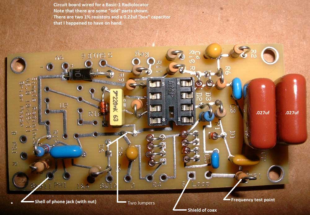
Figure 3
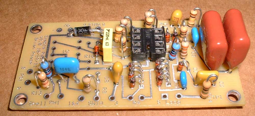
Figure 4
PC BOARD
To reduce mistakes, print out the 3 PDF parts Inventory Sheets Sheet 1, Sheet 2, Sheet 3, then sort and tape all of the parts to sheets 1 and 2 before starting. Mounting the parts on the board is straightforward. Use the Figure 2 for parts placement (Also available as a PDF for printing), with help from Figure3 and Figure 4. If necessary refer to Appendix A for the parts list and the schematics of the Basic-1 and Basic-2, or PDF Basic-1 and PDF Basic-2 for printing. Many part locations are identified on the board. Color codes for the resistor values used are on the inventory sheets and are also listed at the end of the parts list. I learned the color codes while building Heathkits in the 1950's when vacuum tubes were still king, and am giving you the same opportunity! All of the diodes D1 – D14 are polarized and must be oriented with the ends marked with a band placed into the square pads as shown in the layout. All diodes are identical except for D4. Capacitors C4 and C8 are also polarized. They have tiny “+” marks that must go into the square pads. Don't mix up C2 (a 1uf non-polarized ceramic) and C4 (a 1uf polarized Tantalum). Note that C8 has a different value in the Basic-1 than in the Basic-2. The sockets for U1 (and U2 if used) have a notch at the top that must be oriented as shown in the layout. Pin 1 is just left of the notch, where the dot is shown in the layout. This dot also appears on the integrated circuits. Note that C1 is two .027uf capacitors in parallel in the Basic-1, but only a single .068uf cap in the Basic-2, leaving an empty space. If building a Basic-1, do not install D6, R15, R16, R17, U2 or it's socket. Install wire jumpers in place of D6 and R15. Note that the Basic-1 will work if all of these parts are installed, as long as the correct value of C1 is installed. Note that Basic-1 loops will not work properly with a Basic-2 radio or vice versa.
Install 4 inch long wires in all of the holes in the edges of the board except for the 2 loop leads, the -9V lead, and the 2 piezo sounder leads Use a different color for each of the 2 or 3 wires in a group, ie different colors for pads 1, 2, and 3 of SW1. #26 stranded hookup wire is included. Solder the remaining short piece of RG-174 coax to the loop pads, with the shield going to the square pad marked “S”. Again, use a heat sink while soldering the shield, or you will be sorry!
Now use a magnifying glass to check every solder connection for good bonding and no shorts to the ground plane or to each other.
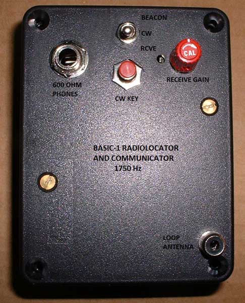
Figure 5
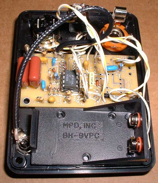
Figure 6
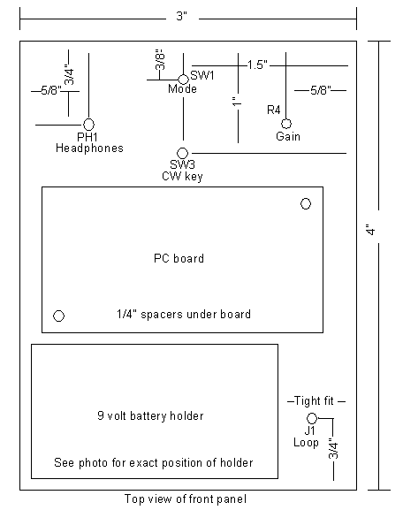
Figure 7
FRONT PANEL
I elected to mount everything on the front panel (except the optional piezo sounder) to make servicing easy, but it is crowded. See Figure 5 and Figure 6. The dimensions shown in Figure 7 will work, but there is essentially zero clearance between the battery holder and J1. After drilling the holes, the trick is to mount J1 first, as close to the left edge as possible, then install the battery holder hard against the other side and the bottom edge with the double-sided tape. The pot & knob, mode switch, phone jack, and push button are easy to mount. Only 2 screws and spacers are needed to hold the PC board. I mounted the piezo sounder with double-sided tape on the right side of the box to make it easy to hold close to my left ear, as I am right handed.
Figure 2 shows the wiring connections to the front panel. Once again use a heat sink and pre-tin when connecting the loop coax to J1. Twist the 2 or 3 wires in each group before soldering and shorten as required, leaving some slack for servicing. They can still be identified by color. The 2 wires to R4 and the wires to SW3 can now be connected without regard to polarity, but not the remaining wires. The 9V+ wire goes to one terminal of SW2 (on the back of R4) and the red wire from the battery holder goes to the other. Now twist the -9V lead around the red wire and then the 9V+ wire, and solder it in the 9V- hole. The wire labeled “Shell” connects to the barrel connection of the ¼ inch phone jack J2, while the other lead connects to the tip. The purpose of this arrangement is to allow measurement of the battery voltage from outside the case by simply connecting a DVM between J2 and one of the screws holding the PC board, with the unit turned ON in CW mode.
Take extreme care when wiring the mode switch SW1. A rear (solder lug) view of the switch is shown both in the layout image and the schematics. The wires are numbered in order on the board except for wire 2, which is directly above the “SW1A” label. Solder them to the like numbered terminals as shown in the switch diagrams. Terminals 1&4 are soldered together and connect to the “1&4” hole on the board. This completes the construction.
FIRST TEST
Install the LF353 or LF412 in each Basic-1, or two LF412 IC's in each Basic-2. The dot on the IC's (pin 1) goes to the left of the notch in the sockets. Install a 9V battery in each unit. It is wise to fasten the bottom of the battery to the holder with a piece of electrical tape to keep it from popping out if the radio is dropped. Plug in the antenna and headphones. In receive mode (switch down towards CW key), inside a building with AC power, you should hear power line harmonics and various other noises. In the CW mode (center switch position), pressing the CW push button should produce a loud 1750 Hz tone in the headphones. This shows that the transmitter is probably working OK. In the pulse mode (switch up), you should hear the same 1750 Hz tone pulsing 5 times/second. If both units work, you should be able to transmit with one and receive with the other. If a DVM (Digital Volt Meter) is available, check the AC voltage across the loop during CW transmit, which should be about 30V rms for the Basic-1 and 60 V rms for the Basic-2. You can check that 2 units are operating close to the same frequency by operating them simultaneously in CW mode with the loops separated by several feet and suspended away from metal objects. Listen with one headset near each ear. You will hear a beat note whose frequency is the difference between the 2 units.
TROUBLESHOOTING
If a unit does not work properly, first double check that there are no short circuits on the PC board. It is very helpful to compare it with a working unit. A visual inspection may reveal a short or a part or wire installed incorrectly. A DVM is required for troubleshooting. They are available for ~$10.00 if you shop around. Voltages can be compared in receive and CW modes and loop and wire continuity can be checked.
If a working unit is not available, then check that the polarity of C4 and C8 are correct and that the ICs are not installed backwards in their socket(s). Check the polarity of all diodes. The ends marked with bands go into the square pads. In the Basic-1 check that wire jumpers are installed in place of D6 and R15. Check the wiring to SW1, which, as I know only too well, is easy to mess up. Make certain that SW1 actually switches as shown in a note on the schematics. Check the wiring of J2. It is easy to mess up if your phone jack has a third solder lug for a switch contact. Make sure that all parts, especially the resistors, are the correct values and installed in the correct locations.
Receive mode tests:
Turn the unit ON in Receive mode, with the loop disconnected, and measure the battery voltage. Next measure from pin 1 of U1A to ground (battery negative) which should be +4.5 VDC. Note that neither J1 or J2 should be used for the ground connection. In a Basic-2, Pins 1 and 7 of U2 should also be 4.5V. R2 and R3 act as a voltage divider to produce the 4.5 volts. Pin 7 of U1B should be about +8V, which reverse biases D1, allowing reception. Pin 6 is held to 0.4V in the Basic-1 and 0.8V in the Basic-2 to force pin 7 of U1B high.
CW mode tests:
When the mode switch is changed to CW, diode D5 is back biased, dropping pin 7 of U1B to 3 VDC, which causes D1 to conduct, preventing U1A from transmitting. The voltage divider formed by R9 and the parallel combination of R10 and R11 produces the 3 volts. Pressing the CW key raises pin 7 of U7 back up to 8 VDC, back biasing D1 and allowing U1A to transmit. Note that U1A will not oscillate with the loop disconnected, but the DC voltages will still be correct.
Beacon mode tests:
In Beacon mode, U1B generates a 5 Hz square wave. This is too fast to register on the DVM as a DC voltage, and too slow for AC. On pin 7, you should see an AC voltage jumping around. If the unit “sort of” works but sounds funny when receiving a signal from the other unit, and the transmitter sound changes when the gain control is turned, then there is something wrong with D7-D14. These diodes limit the voltage across the gain pot R4 to 2 volts peak of either polarity. Either a diode is backwards or defective (open circuit).
If no local help can be found, I am available by email or phone to help with troubleshooting. It would be helpful if you have done the basic troubleshooting described above first.
FIELD TEST OF THE BASIC-1
Find an open area some distance from the nearest power lines. Listen with one unit to see that there is not much power line noise. If a lot of noise is heard, go elsewhere. Support one of the loops vertically against a stick or tree. Put this unit into pulsing transmit mode, then count paces as you walk away along the loops axis, ie you see the full circle of the loop when you look back, not the edge. carry the other unit in receive mode with the loop vertical. Note that the received signal is strongest when your loop is parallel to the transmitter, ie the coaxial orientation. At 67 ft (20 long paces) distance, there should be enough signal to rotate your loop until the pulsing signal disappears. Your loop should be pointed at the transmitter if you are exactly on its axis. At 200 ft (60 paces) range the signal should be weak but audible. For Basic-2 units, these distances are extended to about 100 ft (30 paces) for direction finding and 300 ft (90 paces). Now swap units and repeat the test. If they pass this test they are ready for caving.
Note that the battery voltage
can be measured without removing the screws and opening the box.
Turn the unit on in CW mode, then measure the battery voltage
between J2 and one of the screws holding the circuit board in
place. The radios will function down to about 6 volts, but with
reduced transmit output.
|
|
|
PARTS FOR A SINGLE BASIC-1 UNIT |
*See bottom for Basic-2 |
parts |
|
ITEM |
QTY |
DESCRIPTION |
PART # or SOURCE |
COST |
|
B1 |
1 |
Standard 9V battery |
Local |
----- |
|
*C1A,B |
2 |
.027uf, 3%, 800Vpolypropylene cap |
P14260-ND |
$0.82 |
|
C2 |
1 |
1uf 50V X7R ceramic |
DigiKey 478-4657-ND |
$0.86 |
|
C3 |
1 |
330pf 100V NPO ceramic |
399-4173-ND |
$0.40 |
|
C4 |
1 |
1uf 35V tantalum (16V ok) |
RS 272-1434 478-5812-ND |
$1.89 $0.40 |
|
C5 |
1 |
47pf 50V NPO ceramic |
399-4181-ND |
$0.43 |
|
C6 |
1 |
0.1uf 50V ceramic |
478-3188-ND |
$0.24 |
|
C7 |
1 |
0.22uf 50V ceramic |
399-4288-ND |
$0.65 |
|
*C8 |
1 |
4.7uf 16V tant |
718-1220-ND |
$0.86 |
|
D1-3,5, 7-14 |
12 |
1N914/1N4148 silicon signal diode |
RS 276-1620 |
$2.99/50 |
|
D4 |
1 |
1N4001power diode (or similar) |
RS 276-1653 |
$2.99/25 |
|
*L1 |
~0.9 lb |
332 turns #28 enamel 19.0” dia, ~1750 ft |
Tech-Fixx, Ebay |
$21.60/lb |
|
PH1 |
1 |
Telex 610 series 600 Ohm mono phones |
I have these for sale |
$4.00 |
|
PS1 |
1 |
Piezo speaker (optional) |
RS 273-073 |
$2.19 |
|
R4 |
1 |
1Meg audio taper mini pot with switch |
CT2222-ND |
$3.85 |
|
R1 |
1 |
330 Ohm ¼ W 5% carbon comp resistor |
RS 271-312 |
$9.99/500 |
|
R2,3,9 |
3 |
100K “ “ |
All resistors are in |
|
|
R5, R7 |
2 |
10k “ “ |
The 500 piece |
|
|
R6,12,14 |
3 |
1Meg “ “ |
Radio Shack |
|
|
R8 |
1 |
47 Ohm “ “ |
assortment |
----- |
|
R10 |
1 |
82k “ “ |
(or DigiKey or Mouser) |
|
|
R11 |
1 |
150k “ “ |
$0.06 ea in qty 10 |
|
|
R13 |
1 |
1k |
At DigiKey |
|
|
R15-17 |
3 |
2.2 Ohm “ “ |
|
|
|
SW1 |
1 |
3-way on-on-on mini toggle switch |
Ebay |
$1.00 |
|
SW2 |
0 |
Part of R4 |
--------- |
------ |
|
SW3 |
1 |
Momentary push button, norm open |
M.P.Jones 5019-SW |
$0.29 |
|
U1 |
1 |
LF353 or TL082 dual BiFET op-amp (LF412 is better) |
RS 276-1715 296-7141-5-ND |
$2.19 $0.76 |
|
L1 plug |
1 |
RCA phono plug with cable clamp |
RS 274-451 |
$3.99/6 |
|
L1 jack |
1 |
RCA phono jack with threaded mount |
RS 274-346 MPJA 5522-PL |
$4.19/4 $0.34 |
|
PH1 jack |
1 |
1/4” to fit phones (no switch) |
RS 274-252 |
$4.19/2 |
|
*DIPsocket |
1 |
8 pin DIP socket |
RS 276-1995 A100204-ND |
$0.59 $0.12 |
|
PC board |
1 |
Standard service incl shipping |
ExpressPCB |
$4.25 |
|
Box |
1 |
Plastic box, screw-on lid, 3x4x1.5” high |
M. P. Jones 15523-BX |
$2.49 |
|
B1 holder |
1 |
Snap-in 9V battery holder (tape mounted) |
BH9VW-ND |
$1.30 |
|
Tape |
2” |
Double-sided sticky tape for Bat holder and optional piezo speaker |
Local |
----- |
|
Knob |
1 |
Volume control Knob (R4 has 1/8” shaft) |
See notes below |
----- |
|
Coax |
5.5 ft |
5 ft RG-174 feedline for loop 6” for PC board wiring |
Ebay |
----- |
|
Wire |
6 ft |
#26 hookup wire for PC board 2 ft of 3 colors |
Local |
----- |
|
Shrink Tube |
|
For connections to loop wire |
Local |
----- |
|
Hardware |
2 sets |
4-40 x 1/2” FH screw/nut/spacer 1/8” spacer cut from plastic tubing |
Local |
----- |
|
Hand gnd |
2 ft |
1” wide copper foil |
I have a supply (SASE) |
----- |
|
Tape |
|
Vinyl electrical tape for loop (if required) |
Local |
----- |
|
Circ level |
1 |
Circular surface level for cave loop |
Local |
----- |
|
Line level |
1 |
Line or RV level for surface loop |
Local |
----- |
*Additional parts (and changes) for a single Basic 2 unit
|
ITEM |
QTY |
ADDED OR CHANGED PART |
PART # or SOURCE |
COST |
|
C1 |
1 |
Replace(2).027uf with(1).068uf 3% 400V |
P12083-ND |
$1.68 |
|
C8 |
1 |
Replace 4.7uf 16V tantalum with 3.3uF |
718-1217-ND |
$0.76 |
|
D6, D15 |
2 |
1N914/1N4148 |
See D1 |
|
|
L1 |
~1.9lbs |
309 turns #24 enamel 19” dia, ~1545 ft Replaces the 0.9 lb #28 Basic-1 loop |
Same sources |
Similar/lb |
|
R15-17 |
3 |
2.2 Ohm ¼ Watt carbon film resistor |
RS assortment |
|
|
U1,U2 |
2 |
Must be LF412 for Basic-2 due to high output and low DC offset (see text) |
296-7141-ND |
$0.76 |
|
DIP socket |
1 |
A 2nd 8-pin DIP socket is required |
|
|
Notes: Most of the Radio Shack parts are available from the other suppliers. Mouser.com is another good supplier. DigiKey has other choices for most of the part numbers shown.
Radioshack.com (RS parts)
digikey.com (ND parts)
mpja.com (M.P.Jones parts)
For knobs for 1/4” shafts go to Radio Shack. For 1/8” shafts try allelectronics.com KNB-127 for $1.27 ea, or surplussales.com (KNB)PKG50B1/8 or (KNB)RN-99F1 for $2.00 ea.
M.P. Jones has the 4 ceramic capacitors very cheap.
I have some non-adhesive 1” wide copper foil for the hand ground for free. Send SASE.
I have the Telex 610 Headphones for $4.00 plus shipping.
The circular level is a standard item available in most hardware stores. The line level (designed for hanging on a string) is available at Home Depot. The 3/8” dia cartridge snaps out of the holder. Smaller stick-on levels can be found at an RV/trailer dealer, used to level trailers.
Color codes for the 5% carbon film resistors. There are 4 color bands with the last band being gold, which indicates 5% tolerance. A quick Ohms check with a cheap Digital Voltmeter is a good idea. Sears often has a good meter on sale for $10.00, Harbor freight for $5.00.
|
Resistor |
Value (Ohms) |
Color Code |
|
R1 |
330 |
Orange, orange, brown, gold |
|
R2,3,9,10 |
100k |
Brown, black, yellow, gold |
|
R5 |
10k |
Brown, black, orange, gold |
|
R6,12,14 |
1Meg |
Brown, black, green, gold |
|
R7 |
4.7k |
Yellow, violet, red, gold |
|
R8 |
47 |
Yellow, violet, black, gold |
|
R11 |
150k |
Brown, green, yellow, gold |
|
R13 |
1k |
Brown, black,red,gold |
|
R15-17 |
2.2 |
Red, red, gold, gold |
NOTE: The oriental perception of colors, especially brown and violet, red and orange seems to be different from mine. I have trouble distinguishing between them unless they are side by side.