WITH THE NEW 3496 Hz CLASS-E HIGH_EFFICIENCY BEACON DESIGN
And New Beacon Loop Designs
The DQ Receiver
The new 3-part Printed
Circuit Boards (marked
"2008") include the identical 3-stage receiver RF amplifier board that
has been included since 2003. The main (detector) board has only
two minor changes. The pads for the varactor diode (V1) have been
enlarged to accomodate a surface mount diode. The original
1N5470A diode (with leads) is no longer easily available. See the "README" file for possible sources for the
leaded diode. The second
change is the addition of a voltage regulator to provide 5 Volt or 9
Volt power
to the LCD digital panel meter because only 5 & 9 Volt meters are
readily
available. I have run these meters on 12VDC, but why not do it
right? See COMPLETE INFORMATION
FOR THE UPDATED RECEIVER, BEACON, AND LOOPS 7/30/03 prior to
constructing this receiver, and especially the README
file for updates.
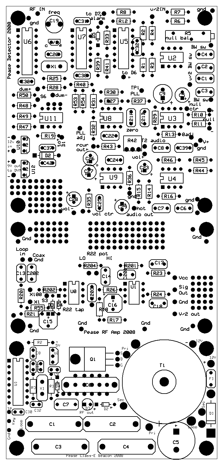
Parts layout of the three PC boards (including the beacon)
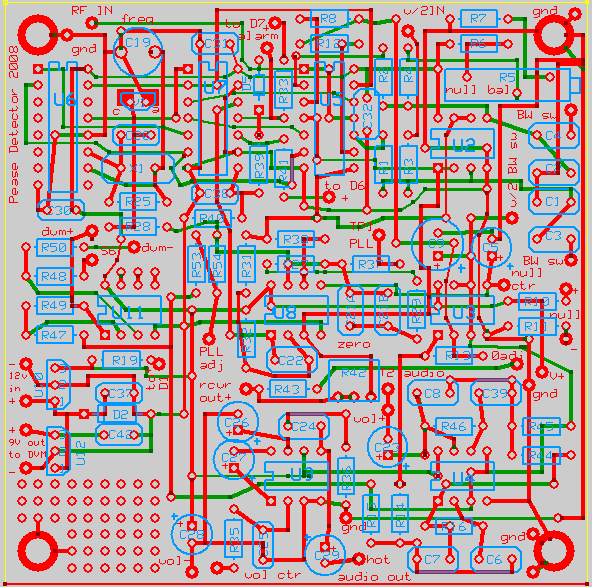
Receiver Detector Board
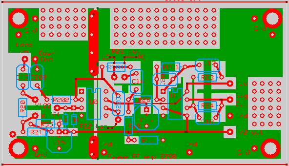
Receiver RF Amp Board
The big change is the beacon
transmitter circuit
board, which is a completely different design. The old
parallel-tuned beacon design, which was technically a Class-E amplifier
with one inductor and one capacitor, has several problems:
Assembly of the 2008 RF amplifier and Detector boards is identical to the older 2003 and 2007 boards (and will not be repeated here) except to mention that the new detector board has space for an on-board 5VDC or 9VDC regulator to power the digital panel meter, which may not be rated to operate on 12 VDC. See the Parts Layout for the two additional parts, U12 and C42, which are located at the extreme lower left corner of the detector board. Due to software problems, the detector schematic has not been updated to show these parts. The panel meter power leads are wired to the new + and - 9V output terminals. The receiver parts list has been updated with correct part numbers (mostly DigiKey and Mouser) and prices.
Warning about the digital panel meters: There are two types (1) those that must use isolated power, i. e. they cannot monitor their own DC power source such as the mpja.com PM438 9VDC unit; (2) those that have a common ground for both the input and 5VDC DC power source, so that they can monitor their own power source such as the mpja.com PM128G-G. All of my receivers until now have used the type (1) meters which should work directly with the new boards. Changes must be made in order to use the 5 V type (2) meters with common ground, which I have installed in some receivers just completed. I first installed a10 V regulator in place of the 12 V unit. I could not find a 10 V regulator, so I used a 9 V unit with two resistors: a 1k 1% between the 5V output and the negative regulator lead; and an 82 Ohm 5% between the negative regulator lead and ground. I then wired the type (2) meter's power leads as follows: Positive lead to +10 V and negative lead to the low impedance V/2 rail at pin 7 of U3B. Warning! You must disable the backlight if your DVM has one, as it draws nearly 50 mA compared to 2-3 mA for the meter itself, which will overload the V/2 rail! On my PM128G-G meters, the backlight was disabled by removing the 24 Ohm resistor R2.
A word about batteries: I chose to power my new receivers with five CR123A lithium cells, which are now available for about $1.00 each online along with sockets. I changed to 10 V regulation (as mentioned in the panel meter note above) to provide more "headroom" as well as directly power the 5 V meters.
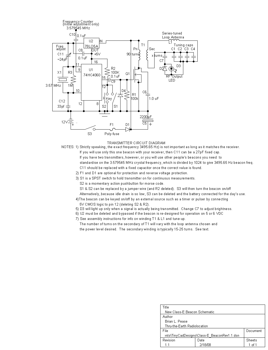
To assemble the 2008 Class-E Beacon board, first install all of the parts that are not involved in tuning. Refer to the parts list. Mount R1, R2, R3, C5, C6, C7, C8, C9, C10, C12, D1, D2, D4, F1, U1's socket, U2, and X1. Note that U2 is installed with its semicircular side facing to the right in the parts layout diagram below. D3 must be installed with the correct polarity (opposite to the polarity of D2). Note that Q1 is specified as an insulated tab MOSFET. Also note that it is a "logic level" gate type that turns on at only 2-3 volts. Ordinary MOSFETS may not fully turn on at 5VDC gate voltage and may heat up! Q1 is mounted with a 4-40 screw or the metric equivalent. A MOSFET with a bare metal tab must use insulating hardware to isolate it from the PC board!, but heat sink compound is useful.
There are 3 choices for C11, which adjusts the frequency of the crystal oscillator. The frequency is only critical if this beacon will be used with other peoples DQ receivers that have the digital field strength readout, or if you own more than one beacon. In either case, the frequency should be set precisely to 3.579545 MHz to match the other beacons using Test Point 1 (TP1) and a good frequency counter. I use a x10 scope probe to avoid loading down TP1. The easiest tuning method is to install a 6-50pF trimmer in either C11 position. I strongly recommend measuring the trimmer's value, then installing fixed COG (NPO) ceramic capacitors in its place. The trimmer's value will shift with time and handling. If this beacon will only be used with your receiver, and especially if the receiver does not have the digital readout, C11 can be a 27pF ceramic cap.
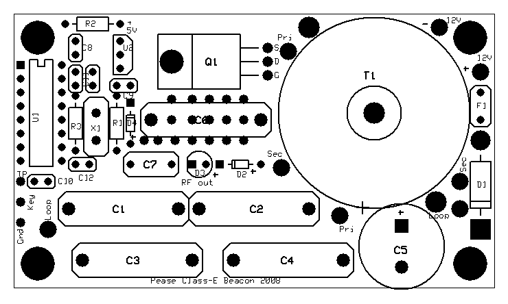
Class-E Beacon Parts Layout
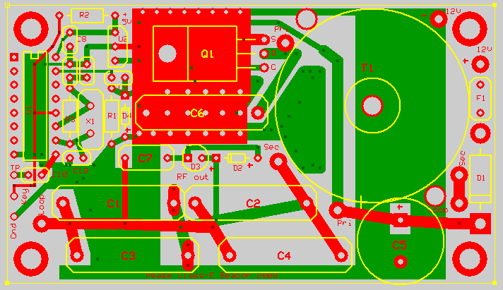
Class-E Beacon PC Board
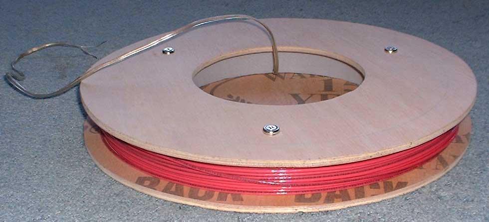
Wind the Primary of toroid T1 (provided) with 90 turns of #20 wire (provided). This is the longer length of smaller wire. Start by feeding half of the length of wire through the center of the toroid core. Now wind one half of the wire onto the core, counting turns. Wind a compact even layer. The easiest technique is to feed a loop through the center hole, then insert a finger into the loop and pull the length of wire through the hole. This is much faster than feeding the wire end into the hole because the wire tends to tangle. The second half will overlap into a second layer, which can be spread out evenly. It is a good idea to leave one lead long (for now) just in case. This will give close to 1242 uH, which is the correct value when C6 is 1uF. Note that these values of L and C deliberately do not resonate close to 3496 Hz even though they form a "tank" circuit. C6 is shorted out for half of each carrier cycle. These values are adequate for power levels from a few Watts up to 10 Watts or so. See the article in Speleonics 25 mentioned above. This winding connects to the two large "pri" holes on the board.
The secondary (link) winding, which feeds the loop antenna, is wound over the top of the primary winding with the shorter length of larger #18 wire, spreading the winding more or less evenly around the toroid. The number of turns required depends on the particular loop antenna chosen; the power level desired; and the battery voltage chosen. The number of turns could vary (typically) from 15 to 25. The smaller number of turns is associated with loops with lower series-resonant resistance, and/or lower power levels. It is easy to tap this winding to allow two or more power levels. The trick is to initially leave a long lead (as much as 1 ft [0.3m]) on one end to allow the easy addition of turns during tune up by unsoldering a single wire. This winding connects to the two "sec" holes on the board
Later, once the beacon is tuned and working properly, T1 can be secured to the board with silicon rubber and one or two tie wraps.
Capacitors C1-C4 are all wired in parallel to series-tune the loop antenna. Often, only one or two capacitors are necessary. Polypropylene capacitors should be used for C1-C4 because they are much lower loss than the smaller (and cheaper) polyester (Mylar) capacitors. If additional small capacitors are needed for precise tuning, they can be be mounted between C1-C4, or under the board. These small capacitors could be polyester because they are such a small part of the total value. A 250 VDC rating is adequate for most wire loops, and for all of the examples given here. Higher Q loops or higher power levels may require a higher voltage rating, up to 600VDC. A capacitor decade box is very useful here. The tuning procedure is to adjust the C1-C4 value to maximize battery current drain and/or AC loop voltage, both of which will occur at the same value of capacitance, or very close to it. Record the final value of DC current. There is no danger of overheating the circuit unless the power level is very high (15-20 Watts). The next section gives several examples of actual loop antennas that were tuned up using a breadboard version of this beacon circuit.
NOTE: Prior to each use of a beacon, it is wise to connect it to the battery and measure the DC current drain to make certain that the tuning is still OK. If the DC current is more than 10-20% lower than the value recorded when the beacon was initially tuned, the tuning should be checked.
Parts layout of the three PC boards (including the beacon)
Receiver Detector Board
Receiver RF Amp Board
- DC current (and heat dissipation) rises rapidly whenever the loop antenna is not precisely tuned to resonance. This can happen during initial tuning; failure of a tuning capacitor; or simply by setting the loop antenna close to a large metal object.
- The 1/16 duty cycle causes large transients that must be absorbed by the zener diode, causing power loss.
- The transients reach the battery, despite the large electrolytic capacitor. The circuit will function properly only on low-impedance batteries such as NiCad, NiMH, or sealed lead acid. This circuit will not function properly on "Lab" type power supplies, even supplies rated at several Amps.
Assembly of the 2008 RF amplifier and Detector boards is identical to the older 2003 and 2007 boards (and will not be repeated here) except to mention that the new detector board has space for an on-board 5VDC or 9VDC regulator to power the digital panel meter, which may not be rated to operate on 12 VDC. See the Parts Layout for the two additional parts, U12 and C42, which are located at the extreme lower left corner of the detector board. Due to software problems, the detector schematic has not been updated to show these parts. The panel meter power leads are wired to the new + and - 9V output terminals. The receiver parts list has been updated with correct part numbers (mostly DigiKey and Mouser) and prices.
Warning about the digital panel meters: There are two types (1) those that must use isolated power, i. e. they cannot monitor their own DC power source such as the mpja.com PM438 9VDC unit; (2) those that have a common ground for both the input and 5VDC DC power source, so that they can monitor their own power source such as the mpja.com PM128G-G. All of my receivers until now have used the type (1) meters which should work directly with the new boards. Changes must be made in order to use the 5 V type (2) meters with common ground, which I have installed in some receivers just completed. I first installed a10 V regulator in place of the 12 V unit. I could not find a 10 V regulator, so I used a 9 V unit with two resistors: a 1k 1% between the 5V output and the negative regulator lead; and an 82 Ohm 5% between the negative regulator lead and ground. I then wired the type (2) meter's power leads as follows: Positive lead to +10 V and negative lead to the low impedance V/2 rail at pin 7 of U3B. Warning! You must disable the backlight if your DVM has one, as it draws nearly 50 mA compared to 2-3 mA for the meter itself, which will overload the V/2 rail! On my PM128G-G meters, the backlight was disabled by removing the 24 Ohm resistor R2.
A word about batteries: I chose to power my new receivers with five CR123A lithium cells, which are now available for about $1.00 each online along with sockets. I changed to 10 V regulation (as mentioned in the panel meter note above) to provide more "headroom" as well as directly power the 5 V meters.
To assemble the 2008 Class-E Beacon board, first install all of the parts that are not involved in tuning. Refer to the parts list. Mount R1, R2, R3, C5, C6, C7, C8, C9, C10, C12, D1, D2, D4, F1, U1's socket, U2, and X1. Note that U2 is installed with its semicircular side facing to the right in the parts layout diagram below. D3 must be installed with the correct polarity (opposite to the polarity of D2). Note that Q1 is specified as an insulated tab MOSFET. Also note that it is a "logic level" gate type that turns on at only 2-3 volts. Ordinary MOSFETS may not fully turn on at 5VDC gate voltage and may heat up! Q1 is mounted with a 4-40 screw or the metric equivalent. A MOSFET with a bare metal tab must use insulating hardware to isolate it from the PC board!, but heat sink compound is useful.
There are 3 choices for C11, which adjusts the frequency of the crystal oscillator. The frequency is only critical if this beacon will be used with other peoples DQ receivers that have the digital field strength readout, or if you own more than one beacon. In either case, the frequency should be set precisely to 3.579545 MHz to match the other beacons using Test Point 1 (TP1) and a good frequency counter. I use a x10 scope probe to avoid loading down TP1. The easiest tuning method is to install a 6-50pF trimmer in either C11 position. I strongly recommend measuring the trimmer's value, then installing fixed COG (NPO) ceramic capacitors in its place. The trimmer's value will shift with time and handling. If this beacon will only be used with your receiver, and especially if the receiver does not have the digital readout, C11 can be a 27pF ceramic cap.
Class-E Beacon Parts Layout
Class-E Beacon PC Board
Wind the Primary of toroid T1 (provided) with 90 turns of #20 wire (provided). This is the longer length of smaller wire. Start by feeding half of the length of wire through the center of the toroid core. Now wind one half of the wire onto the core, counting turns. Wind a compact even layer. The easiest technique is to feed a loop through the center hole, then insert a finger into the loop and pull the length of wire through the hole. This is much faster than feeding the wire end into the hole because the wire tends to tangle. The second half will overlap into a second layer, which can be spread out evenly. It is a good idea to leave one lead long (for now) just in case. This will give close to 1242 uH, which is the correct value when C6 is 1uF. Note that these values of L and C deliberately do not resonate close to 3496 Hz even though they form a "tank" circuit. C6 is shorted out for half of each carrier cycle. These values are adequate for power levels from a few Watts up to 10 Watts or so. See the article in Speleonics 25 mentioned above. This winding connects to the two large "pri" holes on the board.
The secondary (link) winding, which feeds the loop antenna, is wound over the top of the primary winding with the shorter length of larger #18 wire, spreading the winding more or less evenly around the toroid. The number of turns required depends on the particular loop antenna chosen; the power level desired; and the battery voltage chosen. The number of turns could vary (typically) from 15 to 25. The smaller number of turns is associated with loops with lower series-resonant resistance, and/or lower power levels. It is easy to tap this winding to allow two or more power levels. The trick is to initially leave a long lead (as much as 1 ft [0.3m]) on one end to allow the easy addition of turns during tune up by unsoldering a single wire. This winding connects to the two "sec" holes on the board
Later, once the beacon is tuned and working properly, T1 can be secured to the board with silicon rubber and one or two tie wraps.
Tune
Up
The first step in tuneup is to apply
DC power to the
board with the key switch closed (ON), no loop antenna connected, and
an ammeter in series with the battery. The circuit should draw a
low current. My breadboard drew 25 mA (.025 Amps). A high
current indicates that either C6 or the primary of T1 are the wrong
value. A current close to zero indicates that the power MOSFET is
not getting its gate drive, which should be a 5 Volt 3496 Hz square
wave on the "G" pin. Check the operation of the 3.57 MHz
oscillator.Capacitors C1-C4 are all wired in parallel to series-tune the loop antenna. Often, only one or two capacitors are necessary. Polypropylene capacitors should be used for C1-C4 because they are much lower loss than the smaller (and cheaper) polyester (Mylar) capacitors. If additional small capacitors are needed for precise tuning, they can be be mounted between C1-C4, or under the board. These small capacitors could be polyester because they are such a small part of the total value. A 250 VDC rating is adequate for most wire loops, and for all of the examples given here. Higher Q loops or higher power levels may require a higher voltage rating, up to 600VDC. A capacitor decade box is very useful here. The tuning procedure is to adjust the C1-C4 value to maximize battery current drain and/or AC loop voltage, both of which will occur at the same value of capacitance, or very close to it. Record the final value of DC current. There is no danger of overheating the circuit unless the power level is very high (15-20 Watts). The next section gives several examples of actual loop antennas that were tuned up using a breadboard version of this beacon circuit.
NOTE: Prior to each use of a beacon, it is wise to connect it to the battery and measure the DC current drain to make certain that the tuning is still OK. If the DC current is more than 10-20% lower than the value recorded when the beacon was initially tuned, the tuning should be checked.
Examples
of Antennas for the New Beacon Design
This section describes several actual beacon
antennas followed by a
table giving tuning capacitor values and the number of turns on the
link winding for different power levels and operating voltages.
All values are only approximate for loops that you wind. In
particular, the actual PC board should give higher output power and DC
current than the breadboard, which had some thin wiring and several
clip-lead connections. All of the loops are wound with wire
available at Home Depot, Lowes, or electrical wholesalers. It is
insulated, solid or stranded (as indicated), THHN rated, on 500 ft
spools. Unfortunately the cost of copper has doubled
recently. Currently, a 500 ft roll of #14 solid THHN is $30.00 US
while stranded is $35.00. For those outside of the US, #14 bare
copper wire is
about 1.65 mm dia. and #12 is about 2.05 mm dia.. Feedlines for
all of the antennas can be 2-conductor appliance power cord. I
use a few feet of rubber-covered cord with wires of at least #16 (1.3
mm dia.). Because I plan to mount the beacon electronics in the
center of the smallest loop, I fed the loop with a piece of loudspeaker
wire, which is acceptable in such a short length.
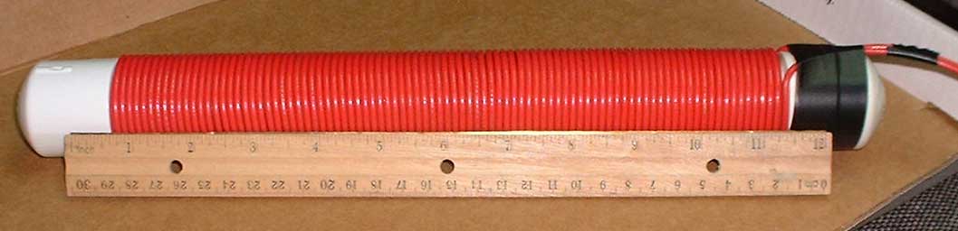
The first antenna is a small wire loop. The winding is 50 turns of #14 stranded THHN wire wound on a rigid form 12" (30.5 cm) in diameter and 1.25" (3.2 cm) wide. Inductance is 1.419 mH for my loop. The loop form is 14" (35.5 cm) dia.. The "filler" ring is some scrap stiff closed-cell foam. A bubble level is installed in the form. Remember that this is just an example. The dimensions are only critical if you wish to make an exact duplicate. There is plenty of room to wind more turns or to use larger wire. This loop is suitable for locations up to perhaps 250 ft (75 m) deep.
12 Inch Loop
The next antenna is 37 turns of #12 solid THHN wire which was initally wound on a plywood wheel which had a circle of nails 22" (56 cm) in dia.. The resulting winding was tightly tie-wrapped every few inches before removing it from the wheel. The inductance is 1.802 mH. The loop is rigid enough to be used by itself without a frame, making it the easiest to construct, cheap, and lightweight for its very strong signal. It can be covered with duct tape or other material to make it even more rugged. It can be made even more rigid by wrapping narrow fiberglass sailboat batten material around its perimeter. The only drawback is the need to carry a line level on a string to level it. Line levels are $1.29 at Home Depot. This antenna will easily do locations 300-400 ft (90-120 m) deep.
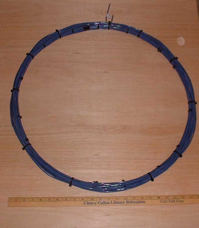
22 Inch Loop
The largest wire antenna is the same 4 ft 4" (1.32 m) dia. loop shown here for use with the old beacon circuit, except that in this design the tap (third wire) is not used. It consists of 18 turns of #14 stranded THHN wire taped every few inches into a circular bundle, then inserted into split plastic wire loom which is used to cover wiring harnesses in vehicles. Mine is 3/4" (2 cm) size, but it is not critical. The loom is then tie-wrapped every few inches. The inductance is 1.30 mH. It can be "figure-eighted" twice to form a bundle small enough for a cave pack. The frame, made from 1/2" (1.3 cm) CPVC pipe and 45 degree elbows, threaded over a loop of shock cord like a tent pole, is required to stretch the loop out for tuning purposes, and to keep it in one plane. The loop is attached with Velcro strips. I no longer use the "stick" legs for leveling as they are too much trouble. It is easier to use rocks or sand. This loop also requires a line level. I have done locations over 600 ft (180 m) deep with this loop!
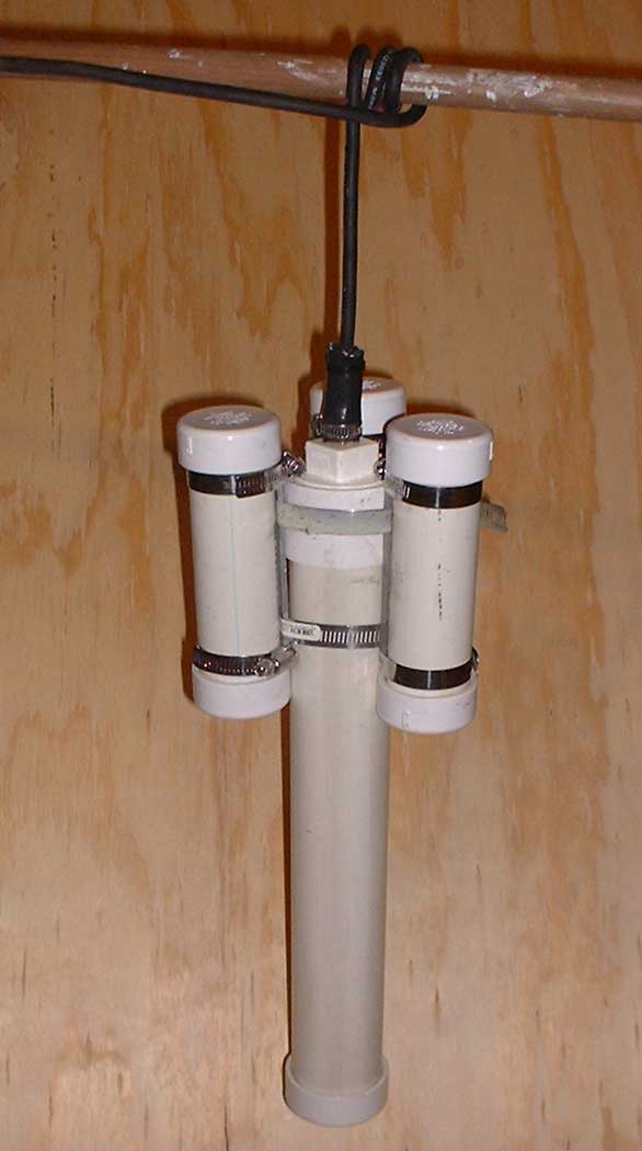
Self-Leveling Ferrite Rod Antenna for Diver Tracking, with Floatation
NOTE: This photo shows a no-no! The SS bands detuned the antenna by acting as shorted turns.
I removed the floats as soon as I figured out what I did!
The final antenna has a ferrite
core. It is used as a self-leveling
loop for caver and diver tracking. This is
NOT recommended for your first beacon antenna! Build and use a
wire loop first! The ferrite core is a model VRF-12C made by
Stormwise.com. The
"rod" is actually assembled from a stack of ferrite toroid cores potted
in a PVC pipe,
with end caps to seal it. It weighs 2 lbs 3 oz (1 kg) without
wire. This assembly is much more rugged (and cheaper) than a solid bare
ferrite rod. The permeability is 850. The assembly is 14" (36 cm)
long. The winding area is 10 7/8" (28 cm) long by 1.32" (3.4 cm)
diameter. I wound 186 turns of #14 stranded THHN wire in
two smooth, tight, layers. The completed loop weighs 3 lbs 7 oz
(1.6 kg). The inductance is 4.375 mH for mine. This antenna is
self-leveling if held by it's feedline, which exits from the top at the
exact center. This makes it possible to track the underground (or
underwater) operator from the surface as he progresses through the
cave! It is possible to do this at depths of 200 ft (60 m) or
more with a skilled operator at the receiver, if the
rod is driven with its maximum power of 6 Watts (0.5 Amps from 12 VDC).
Note: There is a problem with using series-tuned rods for transmitting. The permeability of a ferrite rod used for transmitting will gradually increase as the RMS current through the loop winding increases. This happens far below the level that will saturate the ferrite. This will cause enough increase in inductance to de-tune the loop. The result is that the final loop tuning must be done while transmitting at the power level that the beacon will actually use. The final capacitance value will always be less that the value calculated using the small-signal inductance value such as that obtained with an LCR meter. Another effect of high power is that losses increase, i. e. the Q drops from the small-signal value. What limits the maximum power level is the ability of the circuit to "re-start" after it has been shut off. If the loop has been re-tuned too far at high power, it will present such a high impedance at low power (i.e. when the circuit is again turned on) that not enough loop current will flow to "snap" the lindutance back to its high-power value! In effect, the circuit becomes bi-stable. It can be tuned for a nice high output power (high loop current), but when shut off then turned on again, it operates at a much lower power level and stays that way. I found the maximum power level by trial and error once I understood the problem.
I have also found that this ferrite inductance instability can occur at very low power levels such as an 0.3 Watt unit tested recently. I believe that this may occur because the very high Q at the low power level makes tuning very critical. The trick to making the unit work was to vary the tuning slightly while the DC voltage was varied from 6-13 volts until I found a tune setting where the power level gradually dropped off with voltage as one would expect, instead of an abrupt drop to a very low level.
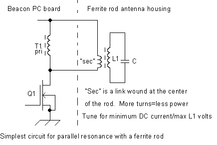
Using parallel resonance with ferrite rods: If a ferrite rod loop antenna is wired for parallel resonance, as shown below, its impedance will drop off-resonance. If the rod has been tuned while transmitting, for minimum DC current/maximum AC loop voltage, then when the battery is connected again there will be an initial AC current surge that will "kick start" the rod by changing its inductance enough to hit resonance. This avoids the "bistable" problem of series resonant operation. The drawback, of course, is that anything that de-tunes the antenna will cause higher DC current and possible circuit damage, just as with the old beacon circuit! In other words, don't set a parallel-resonant antenna on a steel table while it is running!
The first antenna is a small wire loop. The winding is 50 turns of #14 stranded THHN wire wound on a rigid form 12" (30.5 cm) in diameter and 1.25" (3.2 cm) wide. Inductance is 1.419 mH for my loop. The loop form is 14" (35.5 cm) dia.. The "filler" ring is some scrap stiff closed-cell foam. A bubble level is installed in the form. Remember that this is just an example. The dimensions are only critical if you wish to make an exact duplicate. There is plenty of room to wind more turns or to use larger wire. This loop is suitable for locations up to perhaps 250 ft (75 m) deep.
12 Inch Loop
The next antenna is 37 turns of #12 solid THHN wire which was initally wound on a plywood wheel which had a circle of nails 22" (56 cm) in dia.. The resulting winding was tightly tie-wrapped every few inches before removing it from the wheel. The inductance is 1.802 mH. The loop is rigid enough to be used by itself without a frame, making it the easiest to construct, cheap, and lightweight for its very strong signal. It can be covered with duct tape or other material to make it even more rugged. It can be made even more rigid by wrapping narrow fiberglass sailboat batten material around its perimeter. The only drawback is the need to carry a line level on a string to level it. Line levels are $1.29 at Home Depot. This antenna will easily do locations 300-400 ft (90-120 m) deep.
22 Inch Loop
The largest wire antenna is the same 4 ft 4" (1.32 m) dia. loop shown here for use with the old beacon circuit, except that in this design the tap (third wire) is not used. It consists of 18 turns of #14 stranded THHN wire taped every few inches into a circular bundle, then inserted into split plastic wire loom which is used to cover wiring harnesses in vehicles. Mine is 3/4" (2 cm) size, but it is not critical. The loom is then tie-wrapped every few inches. The inductance is 1.30 mH. It can be "figure-eighted" twice to form a bundle small enough for a cave pack. The frame, made from 1/2" (1.3 cm) CPVC pipe and 45 degree elbows, threaded over a loop of shock cord like a tent pole, is required to stretch the loop out for tuning purposes, and to keep it in one plane. The loop is attached with Velcro strips. I no longer use the "stick" legs for leveling as they are too much trouble. It is easier to use rocks or sand. This loop also requires a line level. I have done locations over 600 ft (180 m) deep with this loop!
Ferrite Rod Loop Antenna
Self-Leveling Ferrite Rod Antenna for Diver Tracking, with Floatation
NOTE: This photo shows a no-no! The SS bands detuned the antenna by acting as shorted turns.
I removed the floats as soon as I figured out what I did!
Note: There is a problem with using series-tuned rods for transmitting. The permeability of a ferrite rod used for transmitting will gradually increase as the RMS current through the loop winding increases. This happens far below the level that will saturate the ferrite. This will cause enough increase in inductance to de-tune the loop. The result is that the final loop tuning must be done while transmitting at the power level that the beacon will actually use. The final capacitance value will always be less that the value calculated using the small-signal inductance value such as that obtained with an LCR meter. Another effect of high power is that losses increase, i. e. the Q drops from the small-signal value. What limits the maximum power level is the ability of the circuit to "re-start" after it has been shut off. If the loop has been re-tuned too far at high power, it will present such a high impedance at low power (i.e. when the circuit is again turned on) that not enough loop current will flow to "snap" the lindutance back to its high-power value! In effect, the circuit becomes bi-stable. It can be tuned for a nice high output power (high loop current), but when shut off then turned on again, it operates at a much lower power level and stays that way. I found the maximum power level by trial and error once I understood the problem.
I have also found that this ferrite inductance instability can occur at very low power levels such as an 0.3 Watt unit tested recently. I believe that this may occur because the very high Q at the low power level makes tuning very critical. The trick to making the unit work was to vary the tuning slightly while the DC voltage was varied from 6-13 volts until I found a tune setting where the power level gradually dropped off with voltage as one would expect, instead of an abrupt drop to a very low level.
Using parallel resonance with ferrite rods: If a ferrite rod loop antenna is wired for parallel resonance, as shown below, its impedance will drop off-resonance. If the rod has been tuned while transmitting, for minimum DC current/maximum AC loop voltage, then when the battery is connected again there will be an initial AC current surge that will "kick start" the rod by changing its inductance enough to hit resonance. This avoids the "bistable" problem of series resonant operation. The drawback, of course, is that anything that de-tunes the antenna will cause higher DC current and possible circuit damage, just as with the old beacon circuit! In other words, don't set a parallel-resonant antenna on a steel table while it is running!
| Loop Antenna (see above) |
Tuning cap, uF |
Vdc Volts |
Idc * Amps |
Pin * Watts |
Link Turns |
Loop V * Volts RMS |
Loop I * Amps RMS |
Magnetic Mom * A-T-m sq |
Weight Lbs/kg |
| 12" loop 50 turns |
1.456 uF |
12.7 V |
0.92 A |
11.7 W |
17 |
135 V |
4.33 A |
18.5 A-T-m sq |
4/1.8 |
| 12" loop 50 turns | 1.456 |
12.7 |
0.72 |
9.1 |
15 |
120 |
3.85 |
16.5 |
|
| 12" loop 50 turns | 1.456 |
~6V AA |
0.32 |
1.9 |
15 |
54 |
1.73 |
7.4 |
|
| 22" loop 37 turns |
1.141 |
12.7 |
0.85 |
10.8 |
19 |
142 |
3.59 |
35.6 |
5.8/2.6 |
| 22" loop 37 turns | 1.138 |
12.7 |
0.55 |
7.0 |
15 |
120 |
3.03 |
30.0 |
|
| 22" loop 37 turns | 1.138 |
~6V AA |
0.24 |
1.4 |
15 |
52 |
1.31 |
12.9 |
|
| 4' 4" loop 18 turns |
1.608 |
12.7 |
0.92 |
11.7 |
19 |
109 |
3.81 |
94 |
5.8/2.6 |
| 14" ferrite rod 187 turns | 0.4278 |
~6V AA |
0.09 |
0.54 |
15 |
57 |
0.59 |
2.64 |
3.5/1.6 |
| 14" ferrite rod 187 turns | .4190 |
12.7 |
0.20 |
2.5 |
15 |
117 |
1.22 |
5.42 |
|
| 14" ferrite rod 187 turns | .4190 |
12.7 |
0.26 |
3.3 |
17 |
133 |
1.38 |
6.16 |
|
| 14" ferrite rod 187 turns | .4190 |
12.7 |
0.33 |
4.2 |
19 |
152 |
1.58 |
7.04 |
* NOTE: These values were measured with
a breadboarded circuit and will likely be higher with the actual PC
board.
Antenna
Tuning Table and comparison of a few actual beacon loops with the new
Class-E circuit
For those who care, a method
to calculate the number of link turns needed for any antenna is given
here. Note that if you adjusted your T1 winding to other than 90
turns to obtain the exact inductance, use that # turns instead of
90. The following calculations are for the 5th antenna from the
top of the table above.
If you measure the inductance and the resonant Q of the parallel-tuned loop (ie shorting out the link), you can calculate the series-tuned resistance as just the inductive reactance/Q. For my 22" 37-turn loop I get L=0.51 + j40 Ohms, Q=78 by direct measurement. The link is loaded with ~0.51 Ohms (plus feedline resistance and a bit of cap loss). Mark Mallory's "Z" equation in Speleonics 25 gives the load impedance that the circuit should see directly on the MOSFET drain for a given supply voltage and power level.
If we want 12.7VDC and 0.55A, as in one of my examples, then the desired load Z=29.2 Ohms (across the entire 90 turn winding). Impedance changes as the square of the turns ratio. To convert 29.2 to 0.51 ohms should take a link of sqrt(0.51/29.2) x 90=12 turns. The reality is that 0.51 Ohms is really a higher value, thus the 15 turns specified in my table
If you measure the inductance and the resonant Q of the parallel-tuned loop (ie shorting out the link), you can calculate the series-tuned resistance as just the inductive reactance/Q. For my 22" 37-turn loop I get L=0.51 + j40 Ohms, Q=78 by direct measurement. The link is loaded with ~0.51 Ohms (plus feedline resistance and a bit of cap loss). Mark Mallory's "Z" equation in Speleonics 25 gives the load impedance that the circuit should see directly on the MOSFET drain for a given supply voltage and power level.
Z=[1.2638(Vsquared)]/P
Z=load impedance at MOSFET drain, Ohms: V=battery voltage, Volts: P=battery power drain (Volts x Amps)
Z=load impedance at MOSFET drain, Ohms: V=battery voltage, Volts: P=battery power drain (Volts x Amps)
If we want 12.7VDC and 0.55A, as in one of my examples, then the desired load Z=29.2 Ohms (across the entire 90 turn winding). Impedance changes as the square of the turns ratio. To convert 29.2 to 0.51 ohms should take a link of sqrt(0.51/29.2) x 90=12 turns. The reality is that 0.51 Ohms is really a higher value, thus the 15 turns specified in my table