
The values of C34 and C35 are only approximate.
Brian Pease provides constructional details for his "double quadrature" receiver which is used in conjunction with his radio-location Beacon transmitter.
Introduction
This article gives theoretical and constructional details for a simple high performance 3496Hz long range cave radio beacon receiver which uses what I call a "Double Quadrature" detector. It is used to receive either a steady (non-pulsed) beacon signal for determining location and depth or CW (Morse Code) for passing information to the surface. The complementary beacon transmitter has previously been described in this Journal (Pease, 1996a).
A conventional loop antenna is used to locate "ground-zero". Searching can be aided by signal strength readings if necessary. Once ground-zero is located, depth may be measured by the traditional "null-angle" method and/or by simply reading the signal strength on a digital voltmeter followed by a simple calibration on the surface after the trip or by the latest "ratiometric" method involving the ratio of two strength readings taken at different heights above the surface. The latter methods have allowed a complete "search locate ground-zero find depth" sequence to be completed in 5 minutes by one person on the surface for depths of 50 feet in open terrain. This can result in a happy in-cave crew if a voice down-link is used, as I usually do.
Receiver sensitivity is limited only by the thermal noise of the loop, which will be overcome by atmospheric or power line noise much of the time. If needed, the narrow 1Hz filter has 30dB of attenuation only 17Hz either side of the 3496Hz carrier frequency, which suppresses 60Hz power line interference. 3496Hz is not a good frequency for the UK due to a very close harmonic of 50Hz. The operating frequency can be easily changed if desired. Direct measurement of the transmitted H-field strength is also possible.
Knowledge of
the conductivity of the rock can be used to improve the accuracy of the
depth measurement for depths over 30-40 meters (Pease, 1991; Drummond,
1989). By placing both the beacon and receiver on the surface, a simple
"depth-of-null" measurement allows easy rough estimation of average ground
conductivity for any (approximate) depth. More
conductivity details.
Specifications
Theoretical ultimate range of this
receiver (using headphones for searching) with
my beacon with its small 2-foot diameter loop is 885 metres in
"free space" assuming coaxial loops, 1Hz bandwidth, 10dB s/n ratio, and
no atmospheric or power line noise. The "real world"
range may be quite a bit less, however the PLL and
DC meter will work well below the noise in the 1Hz
bandwidth.
Measured Specifications (12V DC)
The Loop Antenna
A previous article (Pease, 1996b) gives a more detailed circuit description than presented here. That article also included the block diagram. The loop antenna consists of one pound of #29 (American Wire Gauge) enamelled wire wound 18.25 inches in diameter (I got 430 turns), wrapped with electrical tape and mounted on a board. I covered the winding with a (probably unnecessary) electrostatic shield. The second tuned circuit (I1 and C35, shown overleaf) reduces RF amplifier overload from nearby transmitters and power lines, but should not be needed in most situations. The loop is resonated with a 1000pF Arco trimmer plus polystyrene and/or silver mica capacitors. The thermal noise of this antenna determines the maximum sensitivity of the receiver.
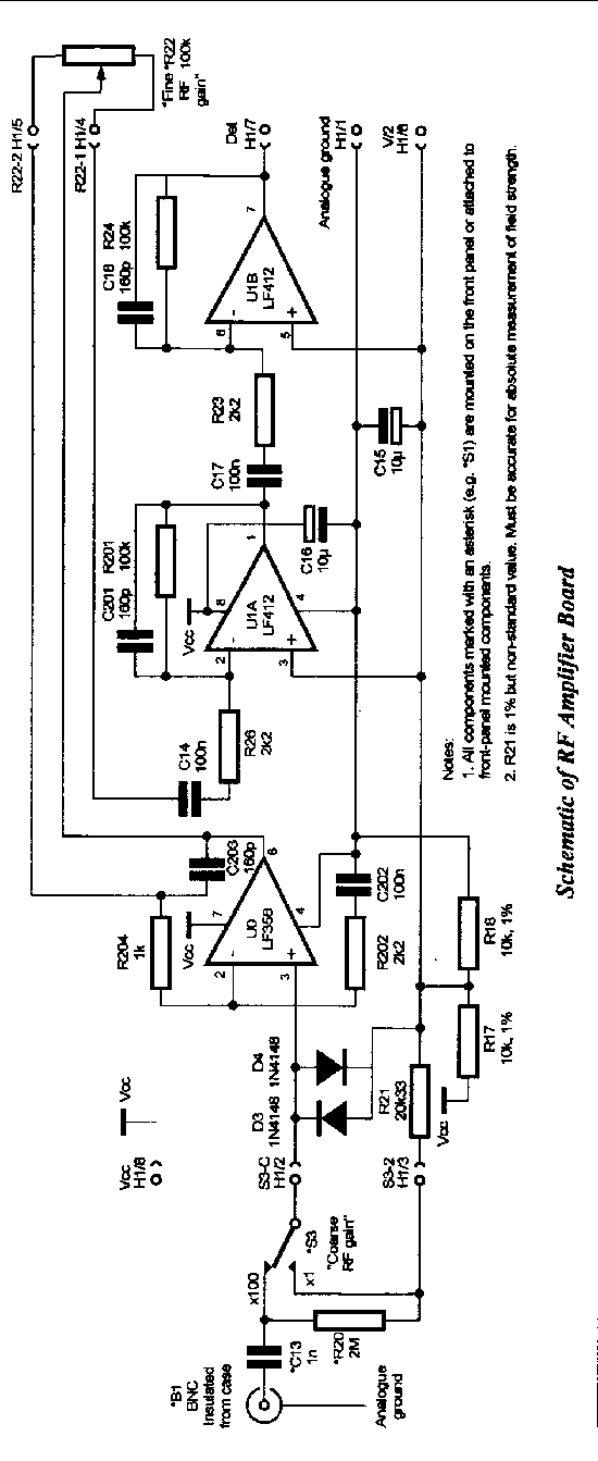
The RF Amplifier
The RF amplifier (U0 & U1) has been upgraded to a 3-stage design with a high impedance input using FET-input op-amps and a unique wide range gain control (R22) which varies the gain of U0 and U1A together. Counting the 40 dB input attenuator the gain can be varied from -4 to +100dB. The circuit has low input noise compared to the thermal noise of the loop . A more sensitive discrete JFET preamplifier was not necessary here, and would not have the repeatable, stable gain of the closed-loop op-amp.
An RF overload LED (D6) utilises an Exclusive-OR (XOR) gate to indicate saturation of the RF amp by atmospheric noise, power line EMI, or the beacon signal. The circuit was empirically designed but the prototype works fine.You may have to adjust the value of R39 to set the threshold of this circuit so the LED starts to flicker at 3.5 V peak (2.5 VRMS) output from the RF amp. One of my receivers uses 27K instead of 10K.
Rf Amplifier Schematic Print it out
to view it. Its unclear on a monitor. image2c.gif, 17 KB.
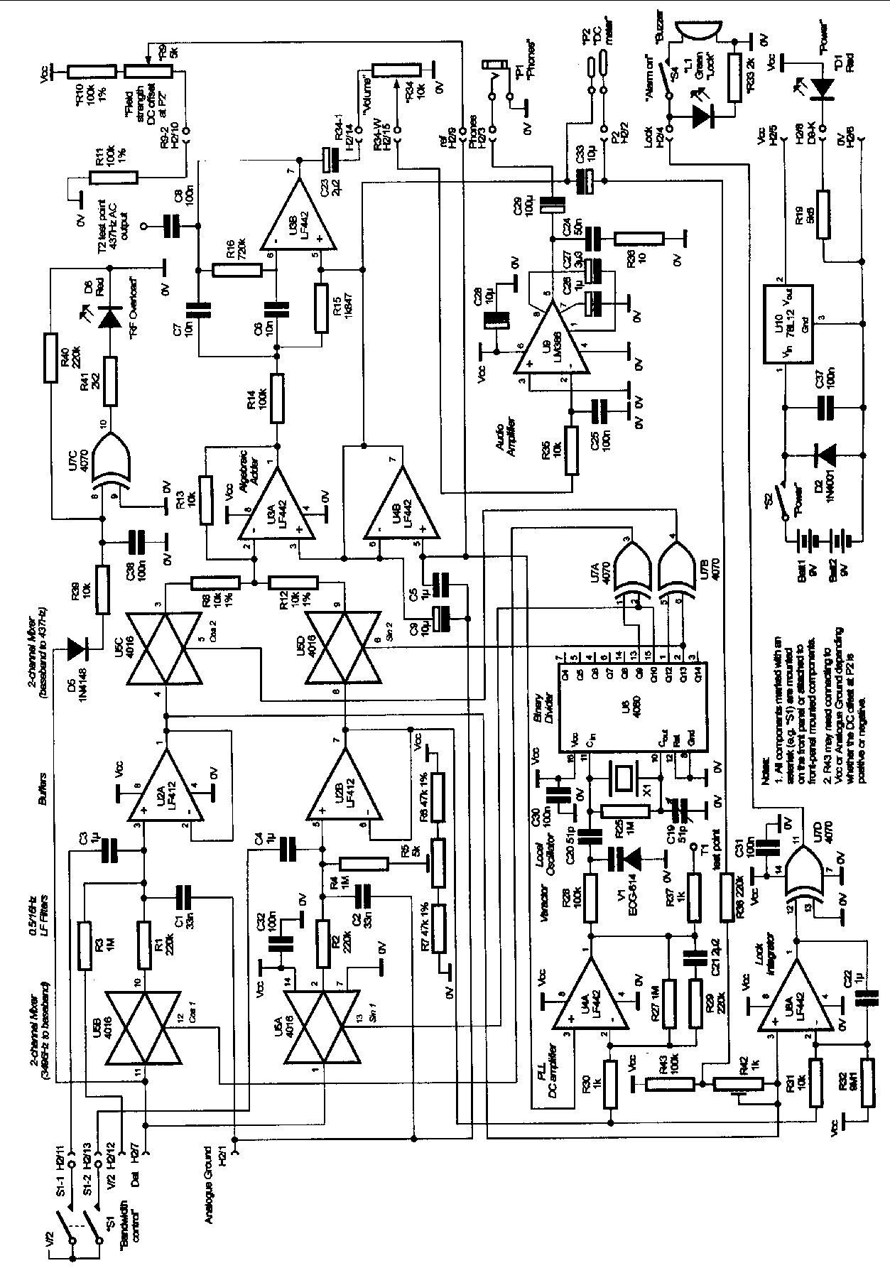
Main Board Schematic Print it out to
view it. use "landscape" orientation. image3c.gif, 63 KB.
The Local Oscillator
The local oscillator (U6) uses a common 3.579545 MHz colour burst crystal which is binary divided in U6 to the 3495.65Hz carrier and 437Hz audio tone frequencies. It is tuned to closely match the Beacon frequency. XOR gates U7 A & B provide the 90 degree phase shifts required by the detector. If a different crystal frequency is chosen then the band-pass filter (U3B) must be changed since the audio frequency will no longer be 437Hz.
The Double-Quadrature Detector
The narrow
band frequency converting detector in this receiver is an improvement on
the 8-pole commutating filter/mixer (my idea, although I never went beyond
the breadboard stage) used in Ray Coles "Organ Cave Radio" (Cole, 1985,
1986; Stevens, 1988). It was built to solve the operational problems of
my "synchronous" receiver which was used for earlier location, depth, and
conductivity measurements (Pease, 1991).
This detector uses a 2-channel in-phase/quadrature direct conversion mixer (U5A & B) whose DC (base-band) outputs are low pass filtered and then up-converted (by U5C & D) to a pair of audio tones whose algebraic sum is proportional to signal strength. The great selectivity results from the fact that the 1Hz bandwidth mode rolls off at -20 dB per decade based on the 0.5Hz bandwidth of the RC filters (R1, C1, C3 and R2, C2, C4). Without the PLL the DC outputs of the two low pass filters will drift slowly with time (one is maximum when the other is zero) but in theory their RMS sum will remain constant. In practice there is about 1dB variation which is inaudible but is annoying for field strength measurements. The combination of the second mixer stage, summer (U3A), and 437Hz band-pass filter (U3B) provide an audio output and allow signal strength measurement with an ordinary AC DVM. The output remains a sine wave even when the input is seriously overloaded which more or less eliminates the need for AGC, limiters, or log amplifiers while searching for ground zero.
The Audio Amplifier
The audio amplifier in the prototype was just a conventional non-inverting op-amp designed for use with my 2kW high efficiency headphones. For the usual low impedance (8-30W ) stereo phones a better amplifier is needed so I designed the LM-386 circuit shown (U9). The new circuit may be more prone to feedback due to the higher currents involved.
The Phase-Locked Loop
A phase-locked loop can be easily added to the D-Q detector to solve the drifting problem by locking the receivers local oscillator to the beacon. The PLLs main purpose is to improve the signal strength readout by allowing the use of a DC meter. It also allows for a "lock alarm" that will alert the operator when a signal is present. It has no other effect on normal receiver operation.
The base-band signal from one channel of the D-Q detector is connected to the input of the high gain DC coupled amplifier U4A (+60dB) whose output drives variable capacitance diode V1 which can slightly shift the frequency of the 3.57 MHz crystal. The total shift at 3496Hz is only 0.14Hz but this is more than enough. Once locked, the SIN (quadrature) signal is nulled out while the COS (in-phase) channel carries a steady DC voltage proportional to the Beacon signal. Extremely narrow loop filtering allows the PLL to lock on signals that are well below the noise and interference in the receivers 1Hz bandwidth and to give a steady readout on a DC DVM. The DC meter has two desirable features: 1) There is an inherent 3dB improvement in s/n ratio over the AC DVM (for the same receiver and meter bandwidth) since the DC meter only sees noise from one channel and 2) the DC bandwidth can be narrowed with a simple RC low pass filter almost without limit to steady the readout. R38 & C33 give a bandwidth of 0.15Hz for an additional 8 dB improvement in s/n ratio. This steady (positive polarity) reading is the best proof that the receiver is phase-locked. In poor conditions, the DC readout is superior to the AC meter, although neither exhibits "drift" while the receiver is locked.
My prototype has a built-in digital panel meter that shares the receivers power source, but requires a differential amplifier to isolate the grounds. This is a 3 1/2 digit unit, 200 mv full scale, 7-12 VDC power. One source is Marlin P. Jones & Assoc. Inc. (800-652-6733) stock no 7516-ME for $11.95. They also have a cheaper unit, stock no 6929-ME for $7.95 that works just as well but only runs on 9 VDC max, so one must add a 3-4 volt zener in series with the power lead to power it from the receiver. To use either meter R33 should be bypassed and C38 deleted and the following circuit added. Note that U8A already exists as an unused op-amp. The 1 Meg resistors MUST be 1% metal films for temperature stability of your "zero". The 5 uf cap is for severe noise and is not normally needed. Both it and the 1 uf unit must be low leakage types, i.e. not electrolytics. The DVM "gain" is set high on purpose in order to obtain high resolution for ratiometric depth measurements.
Lock Indicator and Audio Alarm
To make waiting on the surface less boring I added a circuit to indicate when the receiver phase-locks on a beacon. U8B is an op-amp integrator with a differential input that monitors the base-band (DC) output of both channels. When the in-phase channel rises a few millivolts (positive) above the quadrature channel and holds for several seconds then the integrator output will rise high enough to trip XOR gate U7D and light the "locked" LED, and sound a loud alarm if desired. Its threshold is set higher than the minimum PLL lock-on signal in order to reduce false alarms. It is not foolproof but it has worked fine in field tests so far.
Construction
Ian Drummond laid out a 3-part printed circuit board containing the beacon, original receiver RF amplifier, and receiver. Four boards were made and three are actually working. We may offer some updated boards for sale if there is enough interest. I plan to construct an experimental 874Hz receiver with my board since my prototype 3496Hz unit works just fine. NOTE: 20 updated sets of boards were made and sold. There are a total of 5 working receivers that I am aware of.
For this receiver
to work properly, digital noise, especially the 3496Hz local oscillator
signal, must be kept out of the analogue circuits, particularly the RF
stage, otherwise adjusting the RF gain will affect the detector null. With
the PLL circuit, any 3496Hz or sub-harmonic leakage may cause "lock-up"
on the receivers own local oscillator signal at high RF gain settings and
possible variation in accuracy at different gain settings. The entire radio
must be shielded to prevent feedback to the loop antenna. I dont know
if the loops electrostatic shield is necessary, but I do get extremely
deep nulls at close range (>70dB) and have no "hand" effects. The second
tuned circuit (if used) should be shielded and mounted on the loop to isolate
it from the digital circuitry. I can place the entire receiver, including
my 2kW headphones, at maximum RF and audio gain,
into the centre of the loop without feedback or noise of any kind.
I built the RF prototype amp on its own Radio Shack board and shielded it, along with the input connector (which is not grounded to the case), attenuator, and RF gain control, from the rest of the receiver. The bypass capacitors for +VCC and V/2 (C15 & C16) are also included. I used a 10 turn potentiometer with calibrated dial for RF gain. As a precaution all analogue grounds are brought individually to a single ground lug bolted to the partition separating the RF amp from the main board. Oscillation is always a potential problem with 100dB gain. I placed a shield of grounded foil between the input circuits (B1, S3, etc.) and the RF amp circuit board to eliminate some obvious feedback at maximum gain. I also used a very short coax to connect pin 3 of U0 to the input circuits, with the shield connected only at the input end.
The layout of the main board is not critical except to keep digital signals away from the audio amplifier. Again, in the prototype all analogue grounds are brought individually to a lug on the same bolt holding the RF amp ground lug. The prototype used a RS 2 ´ 3 ´ 5 inch aluminium mini-box for overall shielding, and a belt clip for hands-free operation. Ians custom PC boards require a larger box.
NOTE: The following circuit change MUST be made to prevent oscillation in the 1 Hz mode due to feedback on the V/2 line: Wire the "common" lead of S1 to pin 7 of U4B instead of to V/2.
If the PLL circuits are not being installed then C20 is replaced by a 30pF capacitor connected from pin 11 to ground. V1 along with all parts associated with U4A, U7D, U8B, and the DC DVM output are not installed.
The D-Q detector circuit must be carefully adjusted to null out the 437Hz tone (when no signal is present). If the PLL is not installed then you may have to replace R8 & R12 with a pot to equalise the gain in the two channels to minimise fluctuations in the AC output level when drifting phase causes the signal to shift from one channel to the other. I put the "null" control (R9) on the front panel with a knob and the "null balance" pot (R5) on the circuit card but accessible from outside with a screwdriver. "Null balance" should only need touching up once or twice a day when temperature changes. It will pay to use 1% resistors for all three DC divider networks. The actual values are not critical. The "null balance" pot should be centred before installation to aid in the initial tune-up.
The receiver will work directly from a single 9V battery without a voltage regulator if desired, but there will be significant drift of the null as the voltage drops along with small changes in gain.
Initial Tune-up
Operation
After about two minutes warm-up, I carefully null the receiver, using both null controls, at minimum RF gain and without the antenna. The front panel null control will need adjustment occasionally during the day using the same procedure. With the PLL receiver I just set the loop on the ground; turn on the alarm; switch to 1Hz bandwidth; then increase the RF gain as much as possible without false alarms. I am then free until the alarm sounds when the continuous Beacon signal comes on. If the signal is strong I will use the wide bandwidth mode while searching due to its fast reaction time.Picture of typical searching.
The details of locating a ground-zero and measuring depth by the "null angle" method have been given too many times to repeat here. I use a table giving depth-to-horizontal distance ratios for each 0.5 degrees of loop tilt from vertical (Pease, 1997b). Null angles of 25-40 degrees from vertical should give the best results. With this receiver one has the option of measuring the relative strengths of the horizontal and vertical fields separately, and calculating the null angle as an arc-tangent. This seems to give more accurate results than direct measurement when the null is very shallow (<20 dB).
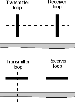
In its simplest form, depth-by-absolute-field-strength requires calibrating the beacon and receiver on the surface after the trip. It also requires some sort of rigid frame for the beacon loop. After locating ground-zero, set the receivers loop horizontally on the ground and switch to the 1Hz mode. Connect the DC DVM and set the RF gain controls so that the RF overload does not light. Record the maximum reading and the exact RF gain and switch settings. Later, set up both loops coaxially on the surface as shown in the illustration on this page. With this geometry the ground has little effect on the signals (at moderate spacing over limestone anyway) so the result will be close to the free-space value. Use the same receiver settings recorded earlier. Now simply adjust the spacing to duplicate the reading obtained at ground zero and measure the distance to obtain the depth.
Coplanar surface calibration, with both loops lying on the surface, is possible, but is restricted to short spacing (perhaps 30-50 meters) as the ground has more effect on the signal than in the coaxial arrangement. Remember that the received signal strength is exactly ½ that obtained with the coaxial arrangement.
Ratiometric depth measurement is perhaps the simplest method overall with no calibration or angle measurements required. Once at ground-zero (precise location is not essential) one simply records the field strength, V1, with the receive loop horizontal then raises the loop a known height, H, (5% of expected depth is a good minimum) and records the strength again, V2. Since it is not necessary to adjust the receivers gain between readings, and only the ratio of the numbers is used, no calibration is required. The RF amplifier must not be overloaded and the beacon signal must remain constant for accurate results. The calculation is a variation of the free-space cubic fall-off equation:

The conductivity of the rock will cause errors in all three of the depth measurement techniques, but good results should be obtained up to a depth of 30-60 meters with any of the methods. In homogeneous (uniform) earth, the null-angle and Ratiometric methods should always give a value less than the actual depth, while the field-strength method should always give a value greater than the actual depth. As depth increases, the spread between the Absolute and ratiometric methods will increase, but the actual depth should always lie between them! At great depths the average of the two values will be closer to the actual depth than either value alone. I have successfully simulated these effects by using a computer program that calculates the effect of conductivity on the strength and direction of the Beacons magnetic field (Pease, 1997a). This article describes all three depth methods and quantifies the effect of conductivity. Using two or three methods is also a good way to pick up careless errors, even at shallow depths!
Feel free to contact me for any details of construction, calibration, or operation. I also have an idea for improving skirt selectivity which I will try when I build my 874Hz unit. I am also available to do locating work using this gear. My contact details appear at the end of this article.
Parts List
| Resistors
(¼W, 5% carbon film except as noted) R1, R2, R29, R38, R40 220K
|
C19 20 to 60pF trimmer
C20 51pF C21 2m F ceramic (could be two 1m F in parallel) C23 2.2m F Tantalum 16V C24 50nF C26 1m F Tantalum 16V C27 3.3m F Tantalum 16V C29 100m F electrolytic C34 7nF (approx) C35 6.8nF (approx) C36 470pF l1 270mH shielded (Not available commercially. Use Mouser 43LJ415 with larger C35 or use a torroid or delete) Semiconductors D1, D6 Red LED D2 IN4001 D3, D4, D5 IN4148 or IN914 L1 Green LED U0 LF356 U1, U2 LF412 U3, U4, U8 LF442 U5 4016 U6 4060 U7 4070 U9 LM386 U10 78L12 (could be ECG-950) V1 ECG-614 or 1N5470A (Varactor diode about 33pF at 4V reverse) X1 3.579545mhz (Color burst crystal) Miscellaneous Alarm buzzer B1, B3 BNC (B1 insulated from case) Batt1, Batt2 9V Header1 8 pin header Header2 16 pin header Loop 18.25" P1, P2 1/8" phone jack S1 DPST S2, S4 SPST S3 SPDT |
References
Cole, Ray (1985) Organ Cave Radio, Speleonics 3, pp2-5.
Cole, Ray (1986) Correction, Speleonics 4, p1.
Drummond, Ian (1989) Ground Conductivity by Electromagnetic Methods, Speleonics 12, pp4-6.
Pease, Brian (1991) Measuring Ground Conductivity With a Cave Radio, Speleonics 16, pp4-6.
Pease, Brian, (1996a) 3496Hz Beacon Transmitter & Loop, CREGJ 23, pp22-24.
Pease, Brian (1996b) The D-Q Beacon Receiver Overview, CREGJ 24, pp4-6.
Stevens, Paul J. (1988) Caves of the Organ Cave Plateau, Greenbrier County WV, "Cave Radio", Appendix G.
Pease, Brian (1997a) Determining Depth by Radio Location: an Extreme Case, CREGJ 27, pp22-25.
Pease, Brian (1997b) This table and any other information desired is available from the author for a self-addressed stamped envelope.